Some trade-offs of a 2-Way Waveguide Speaker played through
# # # # # # # # # # # # # # # # # # # # # # # # # # # # # # #
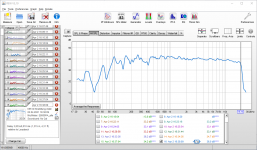
Today, I quickly assembled digital filters for my Hypex FA123 driven Econowave prototype. I meassured indoors gated with Arta and REW, the speaker on a "stand" (table on a table) and corrected the observed FR with Hypex Filter Designer. I was happily listening to the very 'clear sound' until I saw a video on youtube where someone showed his 3-way which was allegedly playing down to only f3 @55, but it sounded fuller than my speaker which was calculated to reach f3 of 35 to 38. Then I realised I forgot baffle step compensation!
I have not done near-field or mic-in-box measurements of the bass response yet so tried a free hand BSC on the go. I ask for your opinions if this is a legit exploit, this is what I did. All corrections up to step 3 concern the woofer channel only:
The speaker has a lot of foundation now, so as a side issue I also reduced the bass boost by 2 dB. WinISD suggest f3 is now at 38 instead of 35 and shows a gentler slope to f6=32 and f10=27. I did this because at low volumes there was already a lot of energy in the room now and I was limiting it so to not get problems with the neighbors, but I was missing presence.
Some introductory remarks in the meantime said:This thread was started to tackle my first and most pressing questions I had when I began working on an Econowave-inspired, Hypex-powered digital 2-Way speaker. Throughout the course of my trials and errors, reading and simultaneous developements elsewhere, I learned some assumptions that where stated by the original developers had to be discarded. Most noteworthy the asymmetric waveguide and the close center-to-center distancing. Using the speakers from a floor level also does not make sense and a much more aggressive EQ-ing could be done. If one is not in pursuit of absolute audio perfection, on could state the question whether it is actually neccessary to use such big boxes. Given that power is cheap and active solutions with DSP abilities are readily at hand and many big commercial manufacturers implement heavy DSPing in ther Pro grade products. Without a doubt, if a passive solution was intended, I would now pursue a floor standing, tall but shallow box, as this is needed for a good position of the image anyway and also due to volume considerations, and would possibly implement a free-stand waveguide on top. With DSP and ample power at hand, I will instead look into minimizing the footprint. This is why my endeavour has not ended and is still in the making. Please understand this thread as an ongoing elaboration of what is actually needed by a certain user-type and what can be achieved with some compromises. Over the time, I will annotate my findings in this post as a list and resource.
# # # # # # # # # # # # # # # # # # # # # # # # # # # # # # #
Today, I quickly assembled digital filters for my Hypex FA123 driven Econowave prototype. I meassured indoors gated with Arta and REW, the speaker on a "stand" (table on a table) and corrected the observed FR with Hypex Filter Designer. I was happily listening to the very 'clear sound' until I saw a video on youtube where someone showed his 3-way which was allegedly playing down to only f3 @55, but it sounded fuller than my speaker which was calculated to reach f3 of 35 to 38. Then I realised I forgot baffle step compensation!
I have not done near-field or mic-in-box measurements of the bass response yet so tried a free hand BSC on the go. I ask for your opinions if this is a legit exploit, this is what I did. All corrections up to step 3 concern the woofer channel only:
- Step 0) REW frequency response shows good crossover (1,2 kHz), cannot see bass response because of room
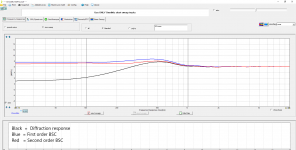
- Step 1) Taking a baffle step simulation from vituixCAD
- suggested values: -6 dB high shelf with center ~ 175 Hz, -2 dB cut at 500 Hz
- Step 2) what I did in Hypex Filter Designer:
- 2a) high shelf, center frequency 160 Hz, Q=0,7, -4 dB
- 2b) cut, center frequency 500 Hz, Q =4, -2 dB
- Step 3) in Hypex Filter Designer:
- add -4 dB gain to compression driver channel to realign both drivers at crossover frequency.
The speaker has a lot of foundation now, so as a side issue I also reduced the bass boost by 2 dB. WinISD suggest f3 is now at 38 instead of 35 and shows a gentler slope to f6=32 and f10=27. I did this because at low volumes there was already a lot of energy in the room now and I was limiting it so to not get problems with the neighbors, but I was missing presence.
Attachments
Last edited:
You said that you equalised the observed response. It seems you may already have done some of it. It wouldn't make sense to simulate it and re-compensate.. or am I missing something?
I did this for the frequencies >1000 Hz, the crossover and the compression driver's response. But I cannot see the actual bass response because of the room. Both drivers match at the crossover frequency (1.2 kHz) and they are time aligned and in phase. So I presume I can work with the frequency response of the woofer as stated by the producer FaitalPRO | LF Loudspeakers | 12PR320 (8Ω) Based on this frequency response I simulated baffle step in vituixCAD and did all the following I described above. My BSC is derived from simulation, based on manufacturer data and I would like to hear if my mental model of is correct and if there is something to account for that I did not think about.
I can more or less see visually through the modes on your measurement so would be able to find a starting point.
Of course BSC should be done using multi-axial measurements. Still, you have to work with what you have.
Of course BSC should be done using multi-axial measurements. Still, you have to work with what you have.
The baffle step calculator assumes that sound radiated to the sides and rear isn't heard at the listening position, and this isn't strictly true in a room. Sound radiated to the sides/rear reflects off the walls and arrives at the listening position, albeit attenuated slightly and with delay (phase shift). This is what causes the roughness in the in-room response; when reflections and directly radiated sound arrives in-phase you see near 0dB (no baffle step) and when they arrive out of phase and destructively interfere you see a null.
Subjectively the smaller the room and/or the closer the speakers are to the walls the less baffle step you need, since more of the sound reflected from the walls arrives at the listening position and the closer to 0dB the peaks will be.
2-3dB baffle step is usually about right for smaller rooms and/or speakers placed closer to walls, and 4-5dB for larger rooms with speakers far away from walls.
You can try equalizing exactly what you measure in-room but the equalization will only be valid for 1 listening position. Using a smooth baffle step compensation but with reduced amplitude will give you something that sounds subjectively balanced at multiple listening positions.
Last edited:
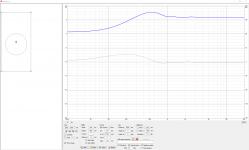
1| Allen: the pictures I provided may have been deceiving. The FR from REW in the original post is before BSC adjustments. But on a different bill is the bass boost at 36 Hz Q=2 +6-8 dB which has nothing to do with BSC and accounts for the too small enclosure (50 net liters). So the bass boost is an independent variable and needs to be there, and this is already in the first FR. See attached WinISD screeny for illustration. Red is +8dB boost, the middle is +6dB, the low one is without EQ vented enclosure tuned at ~32 Hz.
2| TMM, thx, this was just the explanation that I needed to trust my own perception. I reduced the BSC to 3 dB and this makes the midrange appear more balanced.
Then, this moning I dialed back in the 8 dB-boost with the reduced BSC of -3 dB and this sounded more sturdy while it lost mushyness. It was more clear. Can this be true? After I thought about it, this perception does not make too much sense to me but I am not sure. Theoretically, the BSC filter reduces overall efficiency from center frequency 160 Hz up (also a bit below naturally) and bass boost increases efficiency over and around port frequency, say mainly up to 70 Hz. Therefore, both filters linearize the bass response in relation to the lower midrange, whilst the bass boost chiefly affects regions in the border area to sub bass and BSC evenly affects everything up to the midrange spectrum. There might be a small difference in the audio band affected by both filters though. I would have expected that a more powerful lower bass does not add up to clarity, but I think that I hear the opposite. Can this be true?
Attachments

This paragraph is pointless, I forgot to match total levels after I changed BSC and my comparison was impaired by the slight SPL mismatch between both filter setups I suppose.
Then, this moning I dialed back in the 8 dB-boost with the reduced BSC of -3 dB and this sounded more sturdy while it lost mushyness. It was more clear. Can this be true? After I thought about it, this perception does not make too much sense to me but I am not sure. Theoretically, the BSC filter reduces overall efficiency from center frequency 160 Hz up (also a bit below naturally) and bass boost increases efficiency over and around port frequency, say mainly up to 70 Hz. Therefore, both filters linearize the bass response in relation to the lower midrange, whilst the bass boost chiefly affects regions in the border area to sub bass and BSC evenly affects everything up to the midrange spectrum. There might be a small difference in the audio band affected by both filters though. I would have expected that a more powerful lower bass does not add up to clarity, but I think that I hear the opposite. Can this be true?
I notice you are using a 2nd order shelf filter for your BSC. In my experience, a first order shelf is usually a better match for baffle step diffraction loss. You might want to give it a try and see if you like it.
Thank you Jim for your advice. Which center frequency would you choose for a 1st order shelf based on the picture of calculated BS in the original post? Also taking into account that the high peak is equalized with a cut.
It is apparent that your software is not letting you overlay current response/filter response/target response.
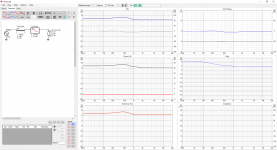
I took your baffle size and duplicated your diffraction response.
It turns out that either a first order or second order shelf filter will do a decent job of baffle step compensation... I was surprised to see that a second order might be superior. It all depends on how each shelf filter interacts with your crossover from woofer to horn.
My VituixCad screen shot shows both filters, I alternated between them using the "short" function.
First order BSC shelf: 141 Hz, 6.4 dB
Second order BSC shelf: 149 Hz, 6.1 dB, Q=0.61
If your play around with these you can probably find a more optimum BSC shelf filter... I spent about 7 minutes fiddling with it.
j.
Attachments
So I found the IIR filters in vituixCAD now, great, they were not on my map. I will give it a try, thank you.
I would like to talk a bit about the thing AllenB brought up
What Allen is getting at is that the Hypex HFD software does not have a target funtion which the user can gererate and overlay on the driver responses.
If you look at my thread,
New active Satori Textreme
You will see that I first developed my filter using direct measurement and experimentation. This is more or less how Hypex recommends. Make measurements, estimate how much EQ is needed to make the drivers flat, load the filter into the amps, measure again... keep going until the drivers seem flat enough, then add the crossover filters.
Around post #106 of my thread I try a different approach. I carefully merge the 4-pi-adjusted near field responses into the gated far field measurements. Then I use VituixCad to simulate the final system response. I develop the filters through iterative simulation. VituixCad allowed me to overlay a target response with the "optimizer" function.
After doing it both ways, I can say this: The measurement+experiment method can work well. A developer can get an acceptable filter stood up pretty quickly. The process of refining it from "acceptable" to "excellent" takes time and experience. I spent all of summer 2020 tweaking, measuring, adjusting, and listening, to get something I felt was truly optimized.
The simulation approach can get a developer to an optimized filter solution much faster. It is a superior way to develop a DSP filter. The measurement+experiment method is a good "quick and dirty" method wich can get us listening to our system with about 3 hours of work. The simulation method takes longer, but the result is fully optimized. How long does it take? for me, about 2 hours for measurements plus about 6 hours of simulation, then another hour of measurements to confirm.
I hope you find this useful...
j.
It is apparent that your software is not letting you overlay current response/filter response/target response.
What Allen is getting at is that the Hypex HFD software does not have a target funtion which the user can gererate and overlay on the driver responses.
If you look at my thread,
New active Satori Textreme
You will see that I first developed my filter using direct measurement and experimentation. This is more or less how Hypex recommends. Make measurements, estimate how much EQ is needed to make the drivers flat, load the filter into the amps, measure again... keep going until the drivers seem flat enough, then add the crossover filters.
Around post #106 of my thread I try a different approach. I carefully merge the 4-pi-adjusted near field responses into the gated far field measurements. Then I use VituixCad to simulate the final system response. I develop the filters through iterative simulation. VituixCad allowed me to overlay a target response with the "optimizer" function.
After doing it both ways, I can say this: The measurement+experiment method can work well. A developer can get an acceptable filter stood up pretty quickly. The process of refining it from "acceptable" to "excellent" takes time and experience. I spent all of summer 2020 tweaking, measuring, adjusting, and listening, to get something I felt was truly optimized.
The simulation approach can get a developer to an optimized filter solution much faster. It is a superior way to develop a DSP filter. The measurement+experiment method is a good "quick and dirty" method wich can get us listening to our system with about 3 hours of work. The simulation method takes longer, but the result is fully optimized. How long does it take? for me, about 2 hours for measurements plus about 6 hours of simulation, then another hour of measurements to confirm.
I hope you find this useful...
j.
Hi Jim
Anyway, I want to thank you. The iterative try-and-error-approach lead me to the result that I attached. This is with a BSC of 3 dB. At 5 dB, the mids begin to occlude the overal tonal transparency and I did not like this, but I prefer the bass boost of 8 dB now, because it adds to the image clarity when the foundation is better. What is not in the chart is some very little extra energy I added for female voices afterwards. I shifted an existing +5 dB PEQ from 2200 to 2300 Hz and dimished the cut at 3400 Hz from -1,5 db to -1 dB. Now, voices and wind instruments have a very gentle presence again but do not sound thin. Anyway, I am happy for now and will try your approach when the sun comes back.
Best
M.
Absolutely, good advice, I didn't know this was possible. When spring reappears—we have a little easter chilldown in northern Germany at the moment—I plan to do propper outdoor measurements: speaker on a high ladder and some stone wool on the ground. I will try to acquire good data and see if I can do it they way you are suggesting it.I hope you find this useful...
I can imagine! I wasted this day again to tweak and tweak and twak, but I wanted to do something else! Did I?I spent all of summer 2020 tweaking, measuring, adjusting, and listening, to get something I felt was truly optimized.
Anyway, I want to thank you. The iterative try-and-error-approach lead me to the result that I attached. This is with a BSC of 3 dB. At 5 dB, the mids begin to occlude the overal tonal transparency and I did not like this, but I prefer the bass boost of 8 dB now, because it adds to the image clarity when the foundation is better. What is not in the chart is some very little extra energy I added for female voices afterwards. I shifted an existing +5 dB PEQ from 2200 to 2300 Hz and dimished the cut at 3400 Hz from -1,5 db to -1 dB. Now, voices and wind instruments have a very gentle presence again but do not sound thin. Anyway, I am happy for now and will try your approach when the sun comes back.
Best
M.
Attachments
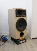
Woofer is FaitalPro 12PR320, compression driver Celestion CDX1-1747 on Dayton H6512 PT-waveguide. Box is 50 net liters but I fancy that because of the inset box for the amplifier module, some smaller airspace at the sides of the this box in the box is rendered less effective. I have to investigate, everything is still very much provisional and will have to be changed many times.
Can someone tell me a bit about multiples of fb?
After I did near-field measurements, I learned about a nasty reponse which do not respond too well to EQ. I do not mean port resonance (oh my god, this will take some time to fix). This problem is lower. If I apply full BSC (6 dB at 190 Hz, Q=0,61), a section between twice fb (the box is tuned to 30 Hz and also has EQ-Boost at 32 Hz) upwards to around 200 Hz shows exagerated increase of power at 5 dB and the worse part is if I use an EQ-cut it with an appropriate Q (2 or 3), even with some tactical distance to the lower bass, perceived bass response seams to be fairly diminished. The box shows a bass response at 29 Hz which is as high as the rest of the band from 250 Hz up, there is bass extension. What is possible is to use higher Q,.I use Cut at 160 Hz Q=4 -3 dB and this helps to shape a bass which is not too muddy. My hypothesis is that between 90 Hz and 200 Hz something is happening that is not the woofer and if I EQ it, I hold back the woofer to much to do it's job. What can I do to investigate this further and is this phenomenon known?
Can you show us a plot of your nearfield woofer response, and also a plot of your nearfield port response?
j.
j.
Below 200Hz it's more the response of the room that you're measuring,
move the mic or the speaker and the lowend measurements will change drastically.
To get a better idea use the Generator(noise) and RTA in REW,
move around with the mic, this way you see live the RTA response.
move the mic or the speaker and the lowend measurements will change drastically.
To get a better idea use the Generator(noise) and RTA in REW,
move around with the mic, this way you see live the RTA response.
I followd your original advice Jim and made some measurements of the driver's response. This led to the insight that the hump is related to box performance in general. Turns out that what WinISD simulates has little to do with actual woofer performance. I'd like to ask you for your opinion which route you would go down.

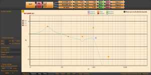
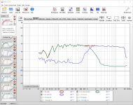
1) First of all, the box is 50 liters net and there is an inset box. I attached an image where you can judge whether this box might compromise bass-reflex performance. The raw performance of the woofer can be seen here https://faitalpro.com/products/files/12PR320/8/12PR320_response_8.gif, so mass roll off begins at ~ 150 Hz. In my attached image below, the black curve is what it perfomes like in the 50 liter 30-Herz vented cabinet. These are near field, dual woofer/port measurements, adjusted for SPL with vituixCAD and corrected for simulated baffle step.

2) I bought an ellbow BR-port from Visaton (Visaton BR25.50). I wanted to shorten it to use a slightly higher fb but in WinISD, everything looked okay if I would tune the box to 30 Hz and then add a PEQ assist at 32 Herz/Q=2/+10dB to it. They write it is 25 cm long which woul result in 31,5 Hz tuning, but actual tuning is around 29, so the flanges or geometry or actual length lowers tuning a bit, compared to manufacturer data. Now WinISD gives me the following, overly optimistic simulation:

As you can see, according to simulation, the long dip below driver's mass roll off should be less than a decibel and the peaking above even less. On the same graph as above, you can see the blue line which represents the above mentioned setting, tuned roughly 30 Herz, assisted at 32. The teal line represents a more modest approach, assisted at 36 Herz. Both have BSC of 6 dB, 190 Hz, Q=0,61 applied
Now the question is what I am looking at. Let me first summarize: the SPL difference with an agressiv assist is up to 7 dB between the deepest part of the long dip below driver mass roll of and the peak above/around it. An option with slightly higher assist location reduces this difference to 5 dB.
A) Actual box size is compromised by the inset box. The areas to the side of the small box lost effectivity. But they are not very narrow, so I thought this would not be an issue. But I lack experience.
B) Bass reflex performance is compromised. Note: The box is sealed with acrylic form inside, no air should be leaking. This is what WinISD tells me about prospected performance with only the vent. This should equal the red line in my chart:

C) The assist is overstreched and the characteristic S-curve is accentuated. I need to use a higher tuning frequency for both vent and assist to get a more even response.
What would you do, based on this data? Maybe I have to build another style of compartment for the plate amp? Or should I shorten the Port and assist higher?
The other question is directed at the value of the current constellation: If I sat the general pass band 3 dB lower than the peak between 100-300 and dip down to 29 Hz and make this the speaker reference, this would get me an uneven bass response with some exaggerated bass and a sub bass still within - dB down to 30 Hz. I heard some slight lift in the bass region can be favorable for subjective listening impression. I could also accept that bass response is 5-6 dB down below 70 Hz and even upper base/lower midrange transition. My question here is whether it is favorable to eliminate this S-curve response in bass, reducing the bass extension but straighten it out, or if the acoustic result is perhaps better this way. If I changed vent/assist combination, I could probably reach 35-40 Hz f3 with a more even response.
Kind regards
m
1) First of all, the box is 50 liters net and there is an inset box. I attached an image where you can judge whether this box might compromise bass-reflex performance. The raw performance of the woofer can be seen here https://faitalpro.com/products/files/12PR320/8/12PR320_response_8.gif, so mass roll off begins at ~ 150 Hz. In my attached image below, the black curve is what it perfomes like in the 50 liter 30-Herz vented cabinet. These are near field, dual woofer/port measurements, adjusted for SPL with vituixCAD and corrected for simulated baffle step.
2) I bought an ellbow BR-port from Visaton (Visaton BR25.50). I wanted to shorten it to use a slightly higher fb but in WinISD, everything looked okay if I would tune the box to 30 Hz and then add a PEQ assist at 32 Herz/Q=2/+10dB to it. They write it is 25 cm long which woul result in 31,5 Hz tuning, but actual tuning is around 29, so the flanges or geometry or actual length lowers tuning a bit, compared to manufacturer data. Now WinISD gives me the following, overly optimistic simulation:
As you can see, according to simulation, the long dip below driver's mass roll off should be less than a decibel and the peaking above even less. On the same graph as above, you can see the blue line which represents the above mentioned setting, tuned roughly 30 Herz, assisted at 32. The teal line represents a more modest approach, assisted at 36 Herz. Both have BSC of 6 dB, 190 Hz, Q=0,61 applied
Now the question is what I am looking at. Let me first summarize: the SPL difference with an agressiv assist is up to 7 dB between the deepest part of the long dip below driver mass roll of and the peak above/around it. An option with slightly higher assist location reduces this difference to 5 dB.
A) Actual box size is compromised by the inset box. The areas to the side of the small box lost effectivity. But they are not very narrow, so I thought this would not be an issue. But I lack experience.
B) Bass reflex performance is compromised. Note: The box is sealed with acrylic form inside, no air should be leaking. This is what WinISD tells me about prospected performance with only the vent. This should equal the red line in my chart:
C) The assist is overstreched and the characteristic S-curve is accentuated. I need to use a higher tuning frequency for both vent and assist to get a more even response.
What would you do, based on this data? Maybe I have to build another style of compartment for the plate amp? Or should I shorten the Port and assist higher?
The other question is directed at the value of the current constellation: If I sat the general pass band 3 dB lower than the peak between 100-300 and dip down to 29 Hz and make this the speaker reference, this would get me an uneven bass response with some exaggerated bass and a sub bass still within - dB down to 30 Hz. I heard some slight lift in the bass region can be favorable for subjective listening impression. I could also accept that bass response is 5-6 dB down below 70 Hz and even upper base/lower midrange transition. My question here is whether it is favorable to eliminate this S-curve response in bass, reducing the bass extension but straighten it out, or if the acoustic result is perhaps better this way. If I changed vent/assist combination, I could probably reach 35-40 Hz f3 with a more even response.
Kind regards
m
Last edited:
Okay, the difference between WinISD and the measured results also comes from differing numbers that I used, I wrote about it here Open Source Monkey Box. The ones Faital supplies with it's datasheet seem to be a little high, 50 sq cm more SD FaitalPRO | LF Loudspeakers | 12PR320 (8Ω)
This does diminish the depth of the bump a bit, now the extended bass shelf and the bump above/at mass roll of would be roughly within 4 dB, if the passband is adjusted to the middle, this could be more acceptable.
This does diminish the depth of the bump a bit, now the extended bass shelf and the bump above/at mass roll of would be roughly within 4 dB, if the passband is adjusted to the middle, this could be more acceptable.
- Home
- Loudspeakers
- Multi-Way
- Digital BSC question