Yeah big speakers are pain in the butt. It took 4 hours to make measurements for the speaker in previous post GIF all 36 both horizontal and vertical, big three way 😀
Even though I don't doubt vituixcad interpolation does as good job as it can my worry is if 3 out of 4 measurements hit to a diffraction null the data does not correlate with the reality. This is just a guess so don't stress about it unless you cannot get the crossover simulated and sound good. Have fun! 🙂
Even though I don't doubt vituixcad interpolation does as good job as it can my worry is if 3 out of 4 measurements hit to a diffraction null the data does not correlate with the reality. This is just a guess so don't stress about it unless you cannot get the crossover simulated and sound good. Have fun! 🙂
Last edited:
I understand now. Before I gather more precise verticals, I need to build a device so not to break my back, speaker and plate amplifier. I can imagine that I hit a null, still, even if the effect is reduced, I think it will remain a major influence on DI and ER.
The speaker always sounded good to my ears. The ears of a layman, who first thought that its the horn driver which make the vocals stand out in the room. And then learned from step response that the woofer was playing a cycle later than it should. If I'd sell speakers to the unknowing, I'd get myself such a speaker, horrible midrange but the singers stand in front of the bass, spectacular SFX! Long story short: I must rely on measurements and now everything looks good but ER, PR and DI, insofar DI includes verticals. That is kind of frustrating.
The speaker always sounded good to my ears. The ears of a layman, who first thought that its the horn driver which make the vocals stand out in the room. And then learned from step response that the woofer was playing a cycle later than it should. If I'd sell speakers to the unknowing, I'd get myself such a speaker, horrible midrange but the singers stand in front of the bass, spectacular SFX! Long story short: I must rely on measurements and now everything looks good but ER, PR and DI, insofar DI includes verticals. That is kind of frustrating.
Attachments
Last edited:
For sure. I don't have enough experience to say how much dip in power because of vertical pattern will affect the listening experience. Might be so that at home there is only miniscule difference in perceived sound and nothing to worry about. Try to simulate some more before new measurements. You could make few different crossover versions and try to listen which you like better.
Last edited:
It seems to me that this is the important question!For sure. I don't have enough experience to say how much dip in power because of vertical pattern will affect the listening experience. Might be so that at home there is only miniscule difference in perceived sound and nothing to worry about.
That's to say: I think it is sounding great now, but I want to optimize. The question ist how much effect the vertical reponse has.
Last edited:
Hello tmuikku,
yes, the vertical measurements are not very detailed. It was a balancing act, you know? The heavy speaker on the table from the balcony, on another device and then turning the monstrum above the edge, on reference axis, matching it with some strokes: I was terrified to break something. Maybe it looks better with more measurements, at least first measurement at 30 degree is still kind of decent. But the interpolations of VituixCAD do not add much distress, they just fill in the blanks.
I think the waveguide is loosing pattern control and this causes the mayor problems. Here is another chart, note ERDI horizontal:
View attachment 951045
Or with vertical removed from DI in options, looks like this. Naturally, ER stays the same:
View attachment 951046
Phase is okay.
View attachment 951049
Hi, sorry somehow didn't see the last comment about phase. Not sure if you got the mid range DI stuff already sorted so you can ignore this post. My previous post didn't mean polarity of a driver but the time delay so I want to expand on this a bit.
I see you are using a delay on the tweeter (post #51) and the delay is set so that tweeter lags the woofer. Try adjusting the delay so that woofer lags the tweeter instead. I mean there is a night and day difference on my simulation with 220us delay on the mid on post #59 so this seems important to me, to get the response right over the crossover region. Small changes to the delay and the DI graph starts to bend. Scroll the delay parameter with mouse wheel and observe how the DI graph changes to find good spot. You'll notice the phases are now in parallel to each other when the DI is smoothest so it helps to monitor the Phase window when you are simulating the crossover.
To align phases of two drivers and get good frequency response on axis and power response the crossover slopes, crossover frequency and delays have to be adjusted right in relation to each other and with the physical properties of the speaker and drivers (your measurements reflect the physical properties). When any of these parameters is off from optimal (what the physical design can achieve) and you will not get the phases perfectly aligned. It is not necessary to perfectly align the phases, but at least try to get them as good as you can to smoothen the DI around crossover. By alignment I mean the phases should be parallel to each other below and above the crossover frequency which again allows you to have smooth DI, power and on axis frequency response.
You could call it quits when the different graphs look good enough or massage the parameters for many days to get all "sixpack" graphs pretty (as well as the physical properties of the speaker allows, or time for another prototype build, or new measurements 😀 ). It might require the high pass be 1123Hz instead of nice 1100Hz etc. small tune ups. This is why I mentioned check your phase. Observing the Phase window graphs help to see if you are getting closer or furher from optimal settings. The phase curves don't have to be exactly top of each other, they can be some constant degrees apart as long as they are in parallel to each other in the crossover region. Being some degrees apart just directs the beam up or down a bit. If you go off-axis on horizontal plane the phases change and this is due to the fact that the horn has acoustic center "deeper" inside the speaker than the woofer. Anyway, I've found it helps to achieve good performance in the simulator by monitoring how the phase curves behave while adjusting the crossover. Have fun!
Last edited:
To add, I cannot say if there is need to massage the "sixpack" graphs into perfection since they might not reflect reality (room acoustics, positioning etc.) and it takes lot of effort to judge what is better ( blind listening tests ). I've found many times a crossover design sounded better than the previous one, and when tried some older designs again they sounded even better so it is a circle jerk unless done blind. Next best option to blind listening tests would be to rely on the measurements and the simulator and tweak the simulation until it is what Toole and others scientific studies have found to sound good, at least get rid of obvious problems like resonances. Luckily VituixCAD supports to achieve this so it is down to measurement quality how close goodness one gets with the physical design at hand.
Last edited:
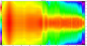
Hi sheeple, I have a question about the horizontal woofer polar plot. It seems like it is showing directivity much lower than one would expect for a 12" woofer. Are we certain those measurements are correct?
Hello Kevmoso,
what can I say: I am a hobbyist with no engineering degree whatsoever. I trust my measurements for a practical use basis*, it is not hard to do. Done without special tools, an individually calibrated Behringer ECM-8000 was used, the soundcard focusrite 2i2 was calibrated to absolute SPL with a DVM, a simple table with 10 degree increment marks from 0 to 90 served as my rotating table. The speaker was carefully pivoted on its horizontal axis 1/2 of the front baffle, but smallish errors are most likely. I still do not think this flaws the measurements. This is what was further done: One single reference axis 1.58 meters above the floor for the purpose of speaker design was used, halfway between woofer and CD, as noted earlier. This adds additional off-axis effects to both drive units if you compared them to data taken from single drivers. Actual center of Faital 12PR320 was -10.5 cm relative to the reference axis, which is an offset of 6 degrees vertical at 1 m measuring distance for all horizontal measurements. The cabinet is 68 cm tall and 34 cm wide, which is quite narrow compared to most other baffles with a 12-inch woofer mounted. If this has some effect I do not know, maybe you have a link for this at hand. There is a characteristical ditch between 600 Hz and 700 Hz which increases the impression of a narrow directivity, but it must be related to either a standing wave on z-axis between front and back (26 cm, ~660 Hz) or a port cancellation above 1st port resonance at 608 Hz. 26.2 cm diameter of effective piston area is correct for the woofer, following the rule of thumb that beaming starts at 1 lamda, 1300 Hertz is where beaming "starts", but what is this defined as? How much SPL loss on which angles define beaming? If there is good insight, I'd be happy if you share. On another website it was noted that actual drivers start to fall of at higher off-axis angles as much as 1 kHz below 1 lamda beaming Please feel free to use the data from post #55 and investigate further.
_________
*sparing the small misalignment of vertical measurements that I had noted before, which is annoying given the dangerous endeavour, but should still be work able because +5cm on x-axis from 1m only inserts a 2.9 degree error which is not nice but hey.
Last edited:

I am going to build the other box soon and I wonder if there are suggestion what I could change for improvements. Dimensions are set but some things can be changed.
- I am investigating a waveguide which has better pattern control for vertical dispersion to solve the directivity problem. If available, I was thinking of a JBL PT-H95HF. It seems that it is happening only because of the limits of the short vertical dimension of the waveguide. I wonder if the B-52 PHRN-1014 waveguide has a better vertical polar response and to which frequency it can hold up the pattern.
- I can shift: 1) The position of the backside amplifier box. This would introduce some asymmetric reflections for the woofer so I am hesitant because I do not know what this does to the dispersion.
- I can shift: 2) The position of the port to one side. Can I expect less resonances with this move? The final speaker will have a higher tuning (36 instead of 32 Hz) and less boost (8 dB instead of 10 dB).
I'm sorry I do not have links to share. I just don't think you should be seeing a ~5db reduction in
off axis output all the way down to 20hz. Unless I am just wrong which is always possible. I too do not have engineering background. Hobbyist all the way here. I wouldn't want to see a fellow hobbyist get too far into a design based on measurements that may be wrong. I am interested in what others have to say on the matter.
off axis output all the way down to 20hz. Unless I am just wrong which is always possible. I too do not have engineering background. Hobbyist all the way here. I wouldn't want to see a fellow hobbyist get too far into a design based on measurements that may be wrong. I am interested in what others have to say on the matter.
Now I understand your concern and I think I know the reason. Could the reason for the problem you see lie in the different domains of this 'too small box', one being it's natural acoustic properties in only 50 liters which result in an early roll off and the other the equalized assist that is not properly represented in this far field measurements? The polar measurements where naturally not taken near field. One remaining problem is that exported from REW they seem not to be gated, that as a side note. Essentially, I use the polars to simulate the higher frequencies and the crossover, which is something that vituixCAD cannot know. The woofer measurements have no BSC correction to it, so to speak, the SPL of the bass frequencies really fall early according to data. Additionally, vituixCAD does not model the effect of a 6th-order vented-assisted system correctly or I did not bother to find out how. The PEQ peak at 36 Hz does not translate into a lift of the total lower section but stands out, also diminishing the other bass regions in the SPL graphs.
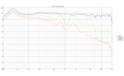
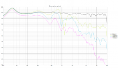
Added some illustrations. I will later show near field and I actually do have a measurement problem, but rather in the crossover region. I could use some help there if this here turns out to be an issue of representation. 1 = with PEQ not normalized, like the image from yesterday but the low peak included, 2 = demonstration of roll off without PEQ and also without BSC, so quite a bit stronger than in reality but it begins quite high still, 4 = with PEQ and normalized, 4 = how vituixCAD works the assist. This is not right, it would be lifted much broader and not be peaky.
Added the 1975 Keele-paper for reference.
Attachments
-
 speaker 68-175_save Power+DI peq.png112.9 KB · Views: 210
 -
 speaker 68-175_save normalized peq.png542.5 KB · Views: 204
 -
 speaker 68-175_save Power+DI no-peq.png110.2 KB · Views: 198
 -
 speaker 68-175_save non-normalized pew.png643.3 KB · Views: 211
 -
Keele (1975-07 AES Published) - New Set of VB Alignments.pdf732.2 KB · Views: 145
Last edited:
So here comes my follow-up question where I could use some help and it is not very complicated. But I lack experience to answer it myself, maybe you can help me understand what I am seeing. The problem is the matching of near and far field measurements. Basically, below the crossover frequency the gated far field data is not very detailed and I am not sure if what I am doing is right.
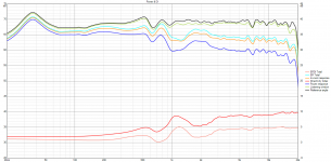
The first image shows the current configuration, albeit that I included an old 'flat response' near field setting measurement (light blue) which I use to mainly show the override with an PEQ, Q=3, +2 dB @750Hz. This was introduced because of crossover effects, but I will explain this with the next pictures. You will see the low frequency section is not perfectly the same, but in general the light blue is close to the current, the biggest difference being the boost which was introduced recently:

I began with a set of complementary LF/HF settings that I EQ-ed for flat response beyond the crossover frequency as far as possible, which in the case of the compression driver is not very far. I then inserted LR4 filters as high pass and low pass and set a delay following the well circulated grimm audio whitepaper https://www.grimmaudio.com/wordpress/wp-content/uploads/speakers.pdf. A delay small of 32us was set for the compression driver for time alignment, which must be the relative acoustic offset of these drivers with the filters applied and an LR4 crossover. This is the result:

There is quite some energy missing above and below the crossover, although it is perfectly in phase.

As can already be seen in the last picture that shows inverted polarity for alignment, I added energy to compensate. Above crossover for the HF-section, I simply disabled two PEQs that where placed for flat response before LR4.

Where I added additional energy below crossover, the frequency response is now peaking 2 dB in the near field measurements, as expected from PEQ:

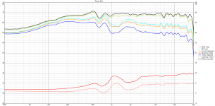
Whereas only the far field measurement shows the characteristical dip between 600 and 700 Hz, which is always at this place when measured from 1 m distance, 4.5us gated, but was even stronger after the application of LR4 filter. As can be seen on the last picture, it is not even so easy to align the far field to the near field measurement but I feel kind of confident that this is a fit, as there are several points where the measurements agree.
What I do not understand why the dip and the peak each do not sho up, while the far field measurement clearly suggest a compensation above and below crossover point, but the near field looks quite peaky as is. What is missed in near field that only shows up on far field or is there something with the far field measurements that is only a ghost?
The first image shows the current configuration, albeit that I included an old 'flat response' near field setting measurement (light blue) which I use to mainly show the override with an PEQ, Q=3, +2 dB @750Hz. This was introduced because of crossover effects, but I will explain this with the next pictures. You will see the low frequency section is not perfectly the same, but in general the light blue is close to the current, the biggest difference being the boost which was introduced recently:
I began with a set of complementary LF/HF settings that I EQ-ed for flat response beyond the crossover frequency as far as possible, which in the case of the compression driver is not very far. I then inserted LR4 filters as high pass and low pass and set a delay following the well circulated grimm audio whitepaper https://www.grimmaudio.com/wordpress/wp-content/uploads/speakers.pdf. A delay small of 32us was set for the compression driver for time alignment, which must be the relative acoustic offset of these drivers with the filters applied and an LR4 crossover. This is the result:
There is quite some energy missing above and below the crossover, although it is perfectly in phase.
As can already be seen in the last picture that shows inverted polarity for alignment, I added energy to compensate. Above crossover for the HF-section, I simply disabled two PEQs that where placed for flat response before LR4.
- 1500 Hz, Q5, -0,5 dB
- 1750 Hz, Q3, -1 dB.
- It was not really enough so after measurements I reduced a PEQ active on the woofer at 1175 Hz
- new 750 Hz, Q3, 2 dB
- 1000 Hz, Q2, +1 to 3 dB
Where I added additional energy below crossover, the frequency response is now peaking 2 dB in the near field measurements, as expected from PEQ:
Whereas only the far field measurement shows the characteristical dip between 600 and 700 Hz, which is always at this place when measured from 1 m distance, 4.5us gated, but was even stronger after the application of LR4 filter. As can be seen on the last picture, it is not even so easy to align the far field to the near field measurement but I feel kind of confident that this is a fit, as there are several points where the measurements agree.
What I do not understand why the dip and the peak each do not sho up, while the far field measurement clearly suggest a compensation above and below crossover point, but the near field looks quite peaky as is. What is missed in near field that only shows up on far field or is there something with the far field measurements that is only a ghost?
Last edited:
sheeple, there is a lot going in your recent posts maybe some of this will help you.
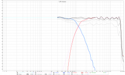
It doesn't seem that the measurements you are using are as good as they could be or at least the processing of them. If you can get 5ms of reflection free time then you should be able to have gated measurements usable to 200Hz or so. In your tweeter measurement it looks to have reflections in it from 1K down so anything you try and EQ below there could well make things worse as you found.
Have a look at a well written guide here
How to make quasi-anechoic speaker measurements/spinoramas with REW and VituixCAD | Audio Science Review (ASR) Forum
and ARTA's application note 4
https://artalabs.hr/AppNotes/AN4-FreeField-Rev03eng.pdf
What you need is one really good set of accurate time locked polar measurements. When you have those Vituix will give you a very good prediction of what you get to the point where full verification measurements will not be needed. You can then try as many different options as you like virtually and audition the results instead of having to measure them again and again. I know it is difficult and will take time but skimping on those will just make getting it right harder.
In your crossover images it looks as if your tweeter has a steeper slope than your woofer. A good way to check this is to generate textbook curves in rephase for the crossover you are trying to achieve and then import them into REW so you can see how close your acoustic slopes are to your desired ones. The grimm approach is to EQ flat two octaves either side and then apply a textbook electrical crossover. I doubt you have been able to EQ your compression driver flat to 2 octaves below 1K which is why the combination is not what you expected.
A textbook Linkwitz Riley crossover will give a power response dip and corresponding bump to the DI as they sum at -6dB instead of -3. A 3rd order Butterworth can sum flat in both axis and power responses but it has it's own tradeoffs.
Sometimes to smooth the power response and DI you might need to make the crossover less textbook and in Vituix you can see the effect of those changes on all the responses simultaneously.
You could also look at this post where there is some information from some old research and the post below that with a link to where kimmo has posted some guidelines on what you do with a two way to get a better DI response.
Crossover filter - Effects on the vertical radiation | Page 2 | Audio Science Review (ASR) Forum
Sorry to link it but it saves me typing it again.
As to the directivity of the woofer it is quite possible that it is correct. The cabinet itself has a large impact of the directivity of the speaker at low frequencies and even a 6" bookshelf can have directivity to 400Hz before going omni quickly so a 12" box could well have directivity to 200Hz before going completely omni.
Getting good clean measurements would help clarifying this too.
Hello fluid,
this was very helpful, thank you. I have seemingly overseen reflections in the measurements, which I originaly put a gate on at 4.5 ms. But in the tweeter measurement 3.7 ms was actually required and the woofer—I suspect the low sitting port which is closest to the floor—creates reflections as early as 3 ms and a gate of 2.7 ms is needed to exclude them. This erases all details I am affraid. I will need to find an indoor place which can accomodate a measuring rig for a big speaker, build a hefty rig and start all over.
Thanks for the hard knowledge, gives an end to a lot of my guessing:
- The formulas in ARTA AN4 are very useful to check where the erroes must have occured. Frustratingly although I thought I could get a sufficient window at home, it seems I need more space than I have at hand right now.
- The insight kimmosto gives into vertical spacing is interesting!
- But also contrary to everything that has been said regarding lobing with Zilch's econowave (Flex Your PCD Mettle: -
Techtalk Speaker Building, Audio, Video Discussion Forum and DIY Waveguide - With questions | Page 3 | AVS Forum). I see you have discussed this at ASR, I must admit I do not understand the part with phase-mismatches, especially because LR-crossovers are supposed to be in-phase? - I did a quick and dirty test of Kimmos approach, dirty because I have not measured the drivers on there respective axis. It shows favorable effect on vertical DI. BUT in my case I wonder about this, because on the vertical plane, the directivity of the drivers I use should not be equal as in Kimmo presents. The woofer must be radiating wider, it matches on the waveguide on the horizontal plane and the waveguide is nominally giving a pattern of 90 x 50 degrees. So I would need to calculate for asymmetric DI with this waveguide. To bad that Kimmo has left this place, because I would love to know how to account for this different application, also with some more precise theoretical foundation.
- But also contrary to everything that has been said regarding lobing with Zilch's econowave (Flex Your PCD Mettle: -
- I have also noted that the slopes are different. The reason is the compression driver falls of sharper and does so increasingly. I will use an LR2 filter on the CD in the future but it will still not be able to follow completely, 5 dB below crossover point (-11 dB) it still departs on a steeper slope.
A quick and dirty test: optimization of vertical DI based on one of Kimmo's suggestions, increased vertical spacing. The crossover (LR2/LR4 electronically, quasi LR4 acoustically) was set higher at 1250 Hz, where 1.2 lambda is 33 cm. This is 6.25 more than the vertical center-to-center spacing of the actual drivers in the actual box, and 60 mm where actually added to the existing 26.5 cm virtually. As the off-axis where gathered around another spacing, some deviations from what is to be expected in reality are introduced. The result:
.png")
compared to

compared to
Great response fluid. Merging of near and far field measurements is imperative to the goals of a complete design.
sheeple your measurements could very well be valid at higher frequencies. I am focused on the low end of your measurements and the ~5ish db reduction in output from 0-90° all the way down to 20hz has to be wrong and I don't think it has anything to do with the enclosure (unless it is very leaky like a cardioidish thing or un-braced cardboard?). Like fluid said, 200hz maybe lower, but at some point omni happens and you get ~0 directivity, definitely not -5db.
To quote/bold fluids statement "What you need is one really good set of accurate time locked polar measurements"
I wish I could be of more help rather than just offering observations...
I will be eagerly following your progress as I think you will likely end up with exceptional results.
Last edited:
Thanks for the nice words Kevmoso (I wonder when it will be done! 😕). I only later understood what you were expecting to see, sorry, I had to have a look at some polar plots again. Kind of forgot how they look in the bass region. Yes, omni looks different, this is weird. I hear plenty of bass, so I am not worried, but it is another inaccuracy to watch out for.
If anyone wants to give me a hint to comprehend the time behaviour of LR4 crossovers, I would be glad. Today, I redesigned the crossover for propper LR4 slopes (not being able to change the measurement situation right now). Before, it was an asymmetric crossover and the compression driver had to be delayed, despite it with the waveguide being physically deeper. With good enough acoustic LR4 slopes, this changed. After the slopes where set up, delay was added to the shorter woofer until cancellation at the crossover showed up as a deep notch. This happened at around 220us, which accounts for 7.8 cm distance. The center of the magnet of the compression driver is at 13.7 cm, which ought to be where the voice coil is, and where the woofer cone and dust cap meet is 5.5 cm behind the front baffle, the difference being 8.2 cm. Pretty accurate! I suppose 7.8 to 8.2 cm line up correct given some unaccounted box/filter behaviour. This distance, 7.8 cm, was also represented in REW measurements, after adding time delay to the woofer, as the distance the woofer is behind the compression driver. Why do I now see the woofer behind the compression driver, after a delay equivalent to the physical offset was added? Despite that it was delayed the very same amount the compression driver is physically leading it. I do not understand this and suppose it has to do with LR4 filter properties. Does someone have a link for me to understand this behaviour?
Now, another thing, this is the step response:

Something that comes with the delay is that I mean to hear a different sonic signature, that I know from earlier XO settings. The compression driver seems to lead decisively, and I mean to hear less driver integration, as if I would focus more on the 'waveguide' itself as a separate source and the higher spectrum actually being separated vertically. Is this a false perception? I do not know criteria for step response of LR4 phase aligned crossovers. In this case here, between peaks maybe 500 us, on 0 time-axis about 290 us. I thought it would be better if both are lets say 50 percent closer to another. This would help with integration I suppose, but ist this right or am I wrong with this?
I also modelled an analogue section comprising of L-pad, protective capacitor and ome HF equalization hoping the components would introduce some useful phase shift, but only 20 us where won this way, in VituixCAD, so in reality it might not even be a thing at all.
If anyone wants to give me a hint to comprehend the time behaviour of LR4 crossovers, I would be glad. Today, I redesigned the crossover for propper LR4 slopes (not being able to change the measurement situation right now). Before, it was an asymmetric crossover and the compression driver had to be delayed, despite it with the waveguide being physically deeper. With good enough acoustic LR4 slopes, this changed. After the slopes where set up, delay was added to the shorter woofer until cancellation at the crossover showed up as a deep notch. This happened at around 220us, which accounts for 7.8 cm distance. The center of the magnet of the compression driver is at 13.7 cm, which ought to be where the voice coil is, and where the woofer cone and dust cap meet is 5.5 cm behind the front baffle, the difference being 8.2 cm. Pretty accurate! I suppose 7.8 to 8.2 cm line up correct given some unaccounted box/filter behaviour. This distance, 7.8 cm, was also represented in REW measurements, after adding time delay to the woofer, as the distance the woofer is behind the compression driver. Why do I now see the woofer behind the compression driver, after a delay equivalent to the physical offset was added? Despite that it was delayed the very same amount the compression driver is physically leading it. I do not understand this and suppose it has to do with LR4 filter properties. Does someone have a link for me to understand this behaviour?
Now, another thing, this is the step response:
Something that comes with the delay is that I mean to hear a different sonic signature, that I know from earlier XO settings. The compression driver seems to lead decisively, and I mean to hear less driver integration, as if I would focus more on the 'waveguide' itself as a separate source and the higher spectrum actually being separated vertically. Is this a false perception? I do not know criteria for step response of LR4 phase aligned crossovers. In this case here, between peaks maybe 500 us, on 0 time-axis about 290 us. I thought it would be better if both are lets say 50 percent closer to another. This would help with integration I suppose, but ist this right or am I wrong with this?
I also modelled an analogue section comprising of L-pad, protective capacitor and ome HF equalization hoping the components would introduce some useful phase shift, but only 20 us where won this way, in VituixCAD, so in reality it might not even be a thing at all.
Attachments
Last edited:
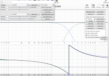
If anyone wants to give me a hint to comprehend the time behaviour of LR4 crossovers, I would be glad.
Why do I now see the woofer behind the compression driver, after a delay equivalent to the physical offset was added? Despite that it was delayed the very same amount the compression driver is physically leading it. I do not understand this and suppose it has to do with LR4 filter properties. Does someone have a link for me to understand this behaviour?
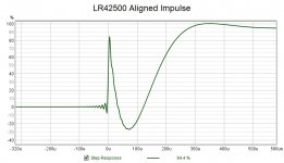
Now, another thing, this is the step response:
There is group delay from the LR4 and phase shift of 360 degrees over the bandwidth. The woofer is also bandwidth limited so it's impulse response peak will appear later.
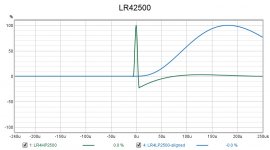
Here is what impulses look like when overlaid and time aligned 2500 LR4
This is the step response of a close to ideal LR4, so you can see it is not so different to yours
You can use the alignment tool in REW to match the phases very easily, attached below due to being a large screenshot
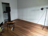
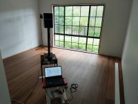
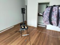
Not necessarily, I have attached some images of a JBL LSR 305 I measured while I was renovating. If the speaker is raised up to be half way between the floor and ceiling, close to the centre of the room and angled towards a corner you get the maximum reflection distance to each surface. The floor and ceiling will be the closest in almost every room. The mic is at 2m in the images but 1m would be usual for this and give a good tweeter measurement after gating.I will need to find an indoor place which can accomodate a measuring rig for a big speaker, build a hefty rig and start all over.
It might be contrary to what has been said but it is not contrary to what actually happens as your quick test showed. If you can't get the CTC distance below 0.5 wavelength (which is hard in most speakers) then 0.5 to 0.7 can be worse than a bigger distance. Trying to cross two sources that have the same effective size will cause a directivity bump but you still see lots of advice to make the waveguide and woofer the same size.But also contrary to everything that has been said regarding lobing with Zilch's econowave
He has moved here VituixCAD v2 - Page 2To bad that Kimmo has left this place, because I would love to know how to account for this different application, also with some more precise theoretical foundation.
But you are unlikely to get a complete explanation out of him so you have to be satisfied with being pointed in the right direction 😉
Attachments
I understand this as an issue how horizontal and vertical axes are weighted. Because even with de DI hump in total ERDI and ER, if we only look at horizontal directivity of a 12-Inch woofer crossed to an even sized 90 degree waveguide, this combination shows great performance. Have a look at my post #60 where the horizontal directivity and and ERDI are plotted together with overall DI and ER. The issue Kimmo tries to solve is vertical DI. And now I would really love to learn more about his arguments, because I am not so sure about the causes of the 'DI hump' in my case. The Dayton H6512 does feature same directivity on the horizontal axis only, on the vertical axis, it is said to only have a 50 degree pattern. At least, it is 29.5cm wide and only 16.5 cm tall. So I quickly tested Kimmos remarks and they show some positive effect, but in a way for the 'wrong' case. It would be interesting to see the vertical DI of another 2-way waveguide speaker with a wider vertical pattern for the compression driver to understand what is actually at work here. Thanks for the LR4 remarks, I trust the crossover more now.Trying to cross two sources that have the same effective size will cause a directivity bump but you still see lots of advice to make the waveguide and woofer the same size.
- Home
- Loudspeakers
- Multi-Way
- Digital BSC question