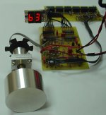
I could not find any relays based attenuator without using PIC microcontroller so I made one.
It's based on CMOS logic IC's and I could acheive maching between absolute dB and both channels better than 0.1 dB.
Total cost is fraction of elma/dact based attenuators which have only 24 positions.
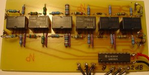
I've used 6 DPDT relays to get 64 steps but it can be easily expanded to 7 or 8 bits (128 or 256 steps) by adding one counter, one 7-segment display and resistors/relays.
More relay boards can be added for multi-channel control.
If somebody from Dubai or UAE is interested in building one, I would be glad to hear from them so we can organise group buy for precision resistors.
It's based on CMOS logic IC's and I could acheive maching between absolute dB and both channels better than 0.1 dB.
Total cost is fraction of elma/dact based attenuators which have only 24 positions.
I've used 6 DPDT relays to get 64 steps but it can be easily expanded to 7 or 8 bits (128 or 256 steps) by adding one counter, one 7-segment display and resistors/relays.
More relay boards can be added for multi-channel control.
If somebody from Dubai or UAE is interested in building one, I would be glad to hear from them so we can organise group buy for precision resistors.
Attachments
Interesting design. Why did you not want to use a PIC? Just curious.
That knob is nice, did you make that?
That knob is nice, did you make that?
Pure logic is nice, but there are Arduino boards - you can easily program them without extended programming skills (no need to program like MCUs - just a few functions in main() {...}, and that's all you need.
By the way, no need to have precise resistors from E192 range - you can get precise values from paralleling/serializing E24 resistors range.
If you need some precise values, i can calculate them for you, and give them in form:
12470 = 470+12000
557 = 680|3100
I've made some simple SQL query to do such calculations, all you have to input is just required value, and preferred resistors count (could be calculated up to 3 resistors in parallel/series)
I still have to learn PIC programming - it's on my list amongst many other projects.
I've got small Proxxon lathe and I made the knob and the spindle which is running on 2 roller bearings.
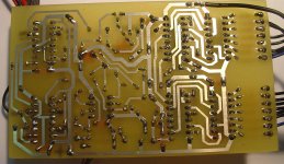
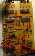
Attached are some more photos.
I've got small Proxxon lathe and I made the knob and the spindle which is running on 2 roller bearings.
Attached are some more photos.
Attachments

Hi witold b, you're not alone. I made attenuator also without MCU, but in different approach, a more clumsy way. See link below.
http://www.diyaudio.com/forums/chip-amps/107196-bananas-pre-inelegant-way-contrl-vol.html
http://www.diyaudio.com/forums/chip-amps/107196-bananas-pre-inelegant-way-contrl-vol.html
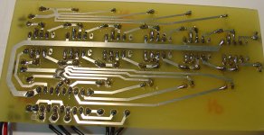
Your boards look very nice; is the yellow one gold plated?
What resistors did you use in your attenuator?
I used 1% metallized types matched to at least 4 decimal places but without paying attention to particular brand/make.
What resistors did you use in your attenuator?
I used 1% metallized types matched to at least 4 decimal places but without paying attention to particular brand/make.
The yellow color was the color of solder resist coating only. That board was immersion silver plated. I used ordinary 1% 1206 chip resistor.
I like your encoder and counter approach, which gives much better tactile feeding between steps than my VR+ADC.
I like your encoder and counter approach, which gives much better tactile feeding between steps than my VR+ADC.
- Status
- Not open for further replies.
- Home
- Source & Line
- Analog Line Level
- Digital attenuator without PIC