Hi all,
I've been building and modifying a DIGI 125 based on infornation in a couple of old threads. The unmodified Circuit is contained in this post.
I originally built the amp with a BC546 for Q3 (VAS) as specified. As described in a couple of other threads, Q3 runs hot enough to be uncomfortable to touch. My test power supply outputs 25-0-25 VDC but I intend to use 35-0-35 VDC on my final amp so I was a little concerned about the temperature of this device. So following the recommendations, I replaced Q3 with a BF469 (TO 126). I also have a BD139 ready to test at a later date. The BF469 runs cool so I achieved what I wanted. I thought I noticed a drop in volume requiring me to turn up the pot a little, but this wasn't done scientifically so its only an impression.
I've built a couple of amps now but I am still a novice and don't quite understand the process for detemining to correct device for a VAS transistor. I just blindly followed others advice which can be dangerous. So here are the important specifications (what I think are important anyway) of the 3 devices mention above.
BC546B
Vceo = 65 volts
Vcbo = 80 volts
Vbeo = 6 volts
hfe = 330
BF469
Vceo = 250 volts
Vcbo = 250 volts
Vbeo = 5 volts
hfe = 114 (measured)
BD139
Vceo = 80 volts
Vcbo = 100 volts
Vveo = 5 volts
hfe = 150 (measured)
Looking at these specifications I would conclude that the BC546B should have been OK using my test PS but probably underrated for a 35-0-35 PS based on Vceo. The BF469 has a significant drop in hfe, so the BD139 should be the better choice.
Can someone suggest other alternatives?
Am I on the right track in selecting these devices or should I be looking at other paramenters?
What is the significance of Vedo?
BTW: I have read many threads which probably contains the answers, but the information was not quite specific enough for me, with my limited knowledge, to understand.
More information contained in these threads:
http://www.diyaudio.com/forums/showthread.php?s=&threadid=2654&highlight=Q3
http://www.diyaudio.com/forums/showthread.php?s=&threadid=8203&highlight=VAS
http://www.diyaudio.com/forums/showthread.php?s=&threadid=3929&highlight=Q3
Thanks
Greg Erskine
HI Greg,
The most important parameter for the VAS is speed.
Not too fast, not too slow, around 100MHz is about right.
You should also have a collector base capacitance not exceeding about 2.5pF.
Beta should be no less than about 60, and it's best to go for something with a dissipation of at least a couple of watts, and around 2.5 times the rail voltage as Vceo.
In closing, don't go for high current devices, as they are slow and usually low beta. Try for a transistor with a maximum collector current no more than 200mA, and more properly, 100mA.
Cheers,
Hugh
Thanks for the feedback Hugh,
I think I follow what you have said.
In short, none of the transistors, BC546B BF469 BD139, really meet all the specifications, as all have one or two undesireable parameters. I've been looking through my catalogues and none of the readily available transistors have the right specifications.
I've been looking for a transistor database on the web that allows me to search for the right specifications. Does one exist?
The search contiues!!
Greg
Hi Greg,
Yes, I think on balance you are quite right. I have found the RS Components and Farnell catalogues a good start point; I did once find a good site on the net, but it's difficult these days to get pdfs of transistor specs - they want payment.
Most of the suitable transistors for VAS are TO126 or TO220 cases, and the best of them, in my view, are the Sanyos.
Sent your package today!! You should have it Wednesday at the latest.......
Cheers,
Hugh
Sorry Hugh, I have a different approach to this than you do.
The VAS is a current gain with a capcaitor across it to achieve a low pass roll-off. In your circuit the capacitor is 150pF.
I recommend:
gating factors
+ Vce (you will need >70V)
+ Ic (you will need >22mA)
+ power dissipation (you will need >500mW)
priorities
+ high beta
+ high ft
+ low Ccb
I don't think package type is important. TO92 is fine provided the transistor is rated for 500mW. I don't think there is any upper limit on desirable ft. You should locate C2 close to the transistor.
You'd be better off replacing the 2k2 resistor with a 10mA CCS both from a performance point of view and from a power dissipation point of view.
You might consider: ZTX653 or 2SD756. There are plenty of others too. I would not recommend BD139.
grege said:Hi all,
I've been building and modifying a DIGI 125 based on infornation in a couple of old threads. The unmodified Circuit is contained in this post.
==============================================
Greg,
I don't understand how you plan to bias your outputs in this way. I have used MJ802 & MJ4502 high current devices and I must warn you about the darlingtion connection.
You typically don't want to put transistors that are not matched in direct darlington connection without emitter resistors, especially in a class AB power circuit because it is very unstable and can pop your outputs. I know these are not the cheapest output transistors so I don't want to see you loose $$$$
😡 😡
What do you know about temp. coefficent compensation?? I am sure you will have to use some sort of bias servo shceme to address this issue on account of these outputs are capable of high power and therefore will get hot.
If you are interested I can post a circuit sketch of a good way to bias these outputs so they work well and are very stable.
It can be done!!!
Zout =4Ohms
hi traderbam,
Thanks alot for your input. You were right on with the level of technical details as I was able to understand it all. 😉
Currently, I have replaced the 2K2 with a bootstrap and was very impressed with the results. I'll probably try a CCS in the future.
Thanks for the recommendations, ZTX653 or 2SD756, I'll have a look at the specifications.
Thanks
hi cunningham,
I've actually used 2SC5200/2SA1943 output transistors and they seem to work fine. This biasing has been done with 3 instead of 2 diodes and the output transistors run cold. When I tried 4 bias diodes the output transistor heated up very quickly, so I realise I need something between the two. I intent to try a proper bias cct in eventually.
I have put a 220 ohm emiter resistor between the two driver transistors if that what you mean, but before I put it in I didn't notice any problem.
There's no temperature compensation at the moment. As everything except the VAS transistor runs cold, at the moment I don't think there is a problem. This is also a future plan when I replace the biasing diodes.
I would appreciate your offer cct for the biasing. I've been looking but haven't really decided on what to use.
I started with this cct (the DIGI125) because it was so simple and actually works. Its been interesting adding parts to it to see how they improve things. Generally, the additional bias diode and bootstraping on the VAS resistor made the most significant differences.
Thanks again
No smoke yet.
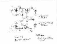
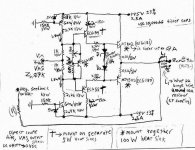
output biasing
Hi Grege,
In this circuit, D1 and D2 are 1A power diodes because they have a forward bias voltage greater than that of the base to emitter juction of outputs. ECG 185 type is the bias servo mounted with the outputs so that the temperature is the same. ECG185 type transistors have beta value close to MJ802 & MJ4502. Temperature coeffiecent is related to beta value. This allows you to adjust the bias on the outputs to just above cuttoff. measure the voltage accross the 0.1 Ohm emitter resistor, with no load. As soon as you see a few milivolts, your good.
The reason I used diodes between the bases of the outputs is explained in the Thevenin equivalent circuit for the AC model of a BJT. (see AC model.jpg on next post)
re is an internal component of a BJT. It is different depending on usually current rating, and gain. Basically, as the NPN transistor conducts more, the voltage on re and RE cause a voltage drop between the output and the NPN base. The emitter of the PNP output is at the potential of the load, or Vout, but the PNP base is pulled up by the two dioes D1 & D2 which drives the PNP output further into cut-off, which is good. As the signal crosses 0V, the voltage between the NPN base and emitter is back to 0.6V because the change in Vbe is porportional to the AC signal. Doing this will make your outputs happy.
The dependent current source (the collector) is dependent on base current and Beta.
By adding an emmitter resistor and base resistor, matching up transistors is not as important because re is not as big of a factor. The percent difference of re is larger than the percent difference of re + RE. True that adding an emitter resistor will reduce the gain, but not having to match componants is much cheaper.
You would drive this circuit with a VAS output of 0VDC and an impeadence of about 6-7000Ohms and a voltage of 23VRMS. By mounting ECG 54 & 55 on two separate 5W heatsinks, their temp. doesn't change very much so thier temperature coefficient is not a factor in the biasing, adding to stability. This is not a true darlington connection because the diodes bias the emitters of the drivers. Usually darlington pairs come in an inegrated package and are perfectly matched transistors inside and of course are always the same temp.
You can use any general purpose transistors for the current sources as long as they can handle 80V. only 100mW though so you might keep them small.
You can drive this circuit pretty hard and it is not likely that you will have any thermal runaway problems from it as long as your heat sink can sink 100W!!
Hope this helps a little.😀 😀 😉
Attachments


I apprepriate your replies cunningham, but I'm extremely busy at work and have 101 problems with my new house, so I hope to study your responses in detail on the weekend.
BTW: My version of winzip is having a problem with your zip files?? Something about version 2.1 ??
Thanks again.
BTW: My version of winzip is having a problem with your zip files?? Something about version 2.1 ??
Thanks again.
grege said:I
BTW: My version of winzip is having a problem with your zip files?? Something about version 2.1 ??
Thanks again.
Download winzip version free trial from download.com
😀
Download winzip version free trial from download.com
Work PC can't do.

I have the latest (and registered copy) at home.
Re: output biasing
cunningham said:Hi Grege,
In this circuit, D1 and D2 are 1A power diodes because they have a forward bias voltage greater than that of the base to emitter juction of outputs. ECG 185 type is the bias servo mounted with the outputs so that the temperature is the same. ECG185 type transistors have beta value close to MJ802 & MJ4502. Temperature coeffiecent is related to beta value. This allows you to adjust the bias on the outputs to just above cuttoff. measure the voltage accross the 0.1 Ohm emitter resistor, with no load. As soon as you see a few milivolts, your good.
The reason I used diodes between the bases of the outputs is explained in the Thevenin equivalent circuit for the AC model of a BJT. (see AC model.jpg on next post)
re is an internal component of a BJT. It is different depending on usually current rating, and gain. Basically, as the NPN transistor conducts more, the voltage on re and RE cause a voltage drop between the output and the NPN base. The emitter of the PNP output is at the potential of the load, or Vout, but the PNP base is pulled up by the two dioes D1 & D2 which drives the PNP output further into cut-off, which is good. As the signal crosses 0V, the voltage between the NPN base and emitter is back to 0.6V because the change in Vbe is porportional to the AC signal. Doing this will make your outputs happy.
The dependent current source (the collector) is dependent on base current and Beta.
By adding an emmitter resistor and base resistor, matching up transistors is not as important because re is not as big of a factor. The percent difference of re is larger than the percent difference of re + RE. True that adding an emitter resistor will reduce the gain, but not having to match componants is much cheaper.
You would drive this circuit with a VAS output of 0VDC and an impeadence of about 6-7000Ohms and a voltage of 23VRMS. By mounting ECG 54 & 55 on two separate 5W heatsinks, their temp. doesn't change very much so thier temperature coefficient is not a factor in the biasing, adding to stability. This is not a true darlington connection because the diodes bias the emitters of the drivers. Usually darlington pairs come in an inegrated package and are perfectly matched transistors inside and of course are always the same temp.
You can use any general purpose transistors for the current sources as long as they can handle 80V. only 100mW though so you might keep them small.
You can drive this circuit pretty hard and it is not likely that you will have any thermal runaway problems from it as long as your heat sink can sink 100W!!
Hope this helps a little.😀 😀 😉
Attachments

- Status
- Not open for further replies.
- Home
- Amplifiers
- Solid State
- DIGI 125 - right VAS selection