parafeed | JLSemrad | Flickr
What is the purpose of the capacitor in the schematic on the right?
Thanks,
John
What is the purpose of the capacitor in the schematic on the right?
Thanks,
John
Last edited:
That is a DC blocking capacitor for the transformer primary.
It is still necessary even though the circuit is symmetric.
The transformer cannot tolerate direct current, and tubes will vary and age.
It is still necessary even though the circuit is symmetric.
The transformer cannot tolerate direct current, and tubes will vary and age.
Last edited:
yes, since with tubes it seldom happens that plate voltages are exactly equal, so a cap is your insurance against dc imbalance...
also igws, the input grids are driven diferentially also...
also igws, the input grids are driven diferentially also...
I figured as much. I guess I was just as curious as to why both triode plates weren't coupled to the transformer primary, inasmuch as the circuit is balanced.
John
John
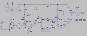
This is differential and parafeed.
That's an interesting circuit. How did it turn out?
Also, how did you calculate the C3?
John
It was only a brainstorming few years ago.
The parafeed feed out is serial LC circuit (let's ignore the rest of other parts of schematic), which have resonant frequency, where its impedance has minimum.
In my practice I strive to keep away any resonant point from required frequency range, if possible at least a decade away. Therefore the LC resonant point near to 2Hz is acceptable.
Usually the transformer primary inductance is given, so parafeed capacitor value can be changed.
The low value (few uF) results higher frequency given breaking point (for example -3dB) and strive slope, the higher value -good- capacitors cost would be enormous.
Each parafeed circuit requires online measuring (usually has bump at lower frequencies) and iteration (simulation never perfect).
you can butt joint your traffo and try it without the cap..
I'm not sure what you mean by "butt-joint".
Thanks,
John
I guess I was just as curious as to why both triode plates weren't coupled to
the transformer primary, inasmuch as the circuit is balanced.
Since it's a series circuit, only one coupling capacitor is necessary.
- Home
- Amplifiers
- Tubes / Valves
- Diffrential Parafeed