Yes you can use much larger caps, as long as they are the right ratio. But then your input Z gets much smaller than what you expect based on the resistors. Normally you try to keep all capacitances as small as practical.
Jan
Jan
Last edited:
Yes, impedance ratio is the same which normally means the cap to resistance value is inverse ratio.
Jan
Jan
...simulations in TI Tina, and my input divider stage dos not attenuate the signal amplitude at all regardless of the frequency (tried 200 MHz max)....?
Does for me (PSpice). Above 1KHz it is near exact 10:1 attenuation. Below 30Hz it is a small hair more (round-off error in your 444.44... resistors).
However as you and Jan say, at high frequency the input impedance gets very-very low due to the roughly 1,000 pFd equivalent input capacitance. A lot of things which actually work OK will work poorly when 10 Ohms reactance (@ 70MHz) loads it.
My C46 should probably be 50pFd, or even 5pFd, with a few-pFd trimmer. And all other caps in proportion. Then input impedance would be hundreds of times higher.
Attachments
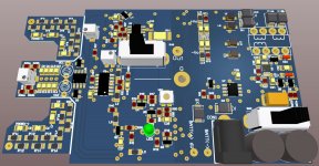
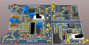
^ OK, as requested... (apologies for low quality images)
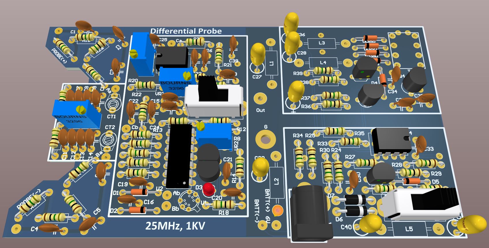
pdf of THP version of the differential probes:
View attachment 391348
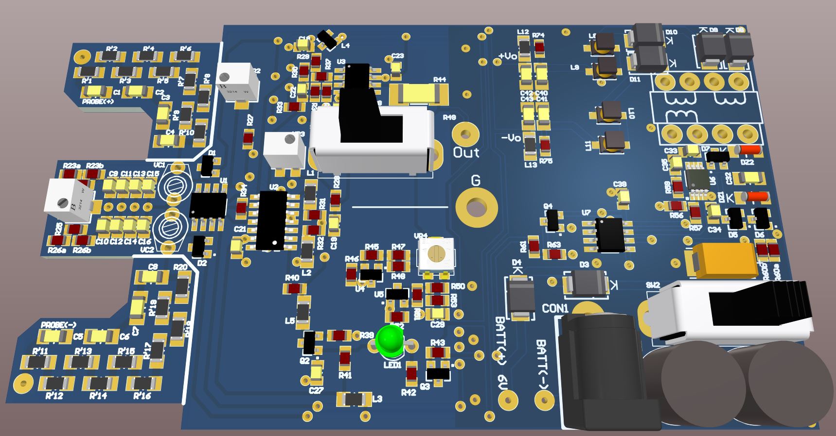
pdf of SMT version of the differential probes:
View attachment 391347
These differential probes I have reverse engineered are:
Testec type: TT-SI9001
1:10 / 1:100 attenuation
25MHz bandwidth.
Input:
±700V @1/100
±70V @1/10
DC & Peak AC
1000Vrms MAX, CAT III
Output:
<= 7V Max into 2K
The supply is 6V (via 4 AA batteries).
Thanks for those schematics, good stuff to learn for me.
I have simulated it in LTspice (used much better opamp instead of 741).
Unfortunately the simulations look like these circuits do not work properly.
-3dB bandwidth is about 9MHz.
Am I missing something?
Nov 2021 Update!
2021 update! Apologies for any mistakes made in the past...
THP version
View attachment Diff Probe THP.pdf
SMT version
View attachment Diff Probe SMT.pdf
God this forum has always been an utter ball-ache when it comes to images!!!!
A
2021 update! Apologies for any mistakes made in the past...
THP version
View attachment Diff Probe THP.pdf
SMT version
View attachment Diff Probe SMT.pdf
God this forum has always been an utter ball-ache when it comes to images!!!!
A
Attachments
Last edited:
Not sure if this will work, but I have put the PCBs on OSHPark and shared them to the public.
Order the THP version of the Differential Probe PCB here:
OSH Park ~
Order the SMT version of the Differential Probe PCB here:
OSH Park ~
Enjoy!
Andy
NOTE: I HAVE NOT TRIED THESE PCBs MYSELF. ORDER AT YOUR OWN RISK!
Order the THP version of the Differential Probe PCB here:
OSH Park ~
Order the SMT version of the Differential Probe PCB here:
OSH Park ~
Enjoy!
Andy
NOTE: I HAVE NOT TRIED THESE PCBs MYSELF. ORDER AT YOUR OWN RISK!

Hi underwurlde, the SMT PCB images have not appeared.SMT PCB Images:


A
It just says attachment.php twice?
Are you able to re-upload the SMT PCB images?
@underwurlde
This article and all the work you did are awesome. I own one of these vintage diff probes, and I am attempting to modify it in order to increase its attenuation from 1:200 to say 1:500. Mine has at 20/200:1 switch (not 10/100:1), but the schematic is almost identical right down to the resistor values.
Studying your latest schematic and how the 10/100:1 attenuation switch changes the common current of the differential halves, rather than increase the values of R13 and R12 (which could introduce a matching error), I was thinking that turning down the overall (common) current might be a better option to increase the attenuation. R18 seems to be the primary setting resistor for this common current, but I have yet to try it out.
What are your thoughts on this modification? Am I on the right track or would you recommend another approach? Thanks for any input.
UPDATE:
Well, I'll correct myself before someone else embarrasses me. Changing R18 does nothing because that circuit merely turns on the current mirror via Q2 and Q1 and has no affect on its current. I therefore had to explore the initial approach of adjusting R12 and R13. I found that if I changed them to 5.6k ohms, I was able to attain a 500:1 attenuation ratio almost right down to the volt as compared to a Fluke meter.

Well, I'll correct myself before someone else embarrasses me. Changing R18 does nothing because that circuit merely turns on the current mirror via Q2 and Q1 and has no affect on its current. I therefore had to explore the initial approach of adjusting R12 and R13. I found that if I changed them to 5.6k ohms, I was able to attain a 500:1 attenuation ratio almost right down to the volt as compared to a Fluke meter.

Hi , for the smt version probe, someone know IC6 parts number ?SMT PCB Images:
A
- Home
- Design & Build
- Equipment & Tools
- Differential Probe - Reverese Engineered