> You could double or triple the values of the Cs and add series Cs but what should that bring ?
Precisely what I wanted to understand and why they are all doing it in CBs (Funkamateur).
Perhaps to have the ability to tune to the exact desired frequency which is not important for audio.
Show me a photo. Maybe I can help you with some ideas. Am mechanical by profession.
Thanks, this is the motherboard, analog filter boards will be mounted on the back side.
Ground connections will be made via the "Abstandshalter".
The motherboard will be mounted in a frame that fits a case from W&G.
I have a milling machine and could make my own design case but the machine allows only 6 mm max. tools and it is a lot of work...

> Measured: Supply +/- 2,3 V, junction of 1k and FET + 1,1 V.
I asked because I want to just use +5V and Gnd, like Elso Kwak. I think I will, as I want to use an additional buffer, like Jim Hageman's Hagclock.
> Perhaps to have the ability to tune to the exact desired frequency which is not important for audio.
I recalculated everything today based on the balanced circuit, 22MHz and using J310 JFETs. I would end up with either 110p/110p (100p/120p) for feedback plus 220p from gate to Xtal on each half, or feedback caps only 91p (82p/100p). So your values are not far off. My Xtal has 22p CL, and 35R Ri, according to Segor.
Patrick
You have PM regarding custom housing.
Thanks, I have planned everything and have the case already.

Like this one ?
Yes, but a bit higher, I meant PJG-4.
Like in the picture I will use for PSU.
The ADCMP567's Vdd is specified 2,5 V to 5 V.
If theoretically Vdd would be ground, the output would be exactly MC100 NECL level.
Another coincidence.
I wonder if the chip would do it...
If theoretically Vdd would be ground, the output would be exactly MC100 NECL level.
Another coincidence.
I wonder if the chip would do it...
At 4 euros a piece, you can afford to test.
Where ?
Did you see the EP series ? Works from 5 V and 3,3 V. Flipflop and buffer are faster than EL series, have jitter specified = 0,2 ps.
I reviewed all my datasheets and found some new coincidences.
EP series: Jitter +/- 20% = propagation delay / 1000 --- EP11: 220 ps = 0,2 ps
E / EL series: Jitter +/- 20% = propagation delay / 500 --- E131: 500 ps = 1 ps
ELT / EL series with large swing: Jitter +/- 20% = propagation delay / 100 --- ELT23: 3500 ps = 35 ps
> Where ?
OK 5.50 at Digikey. You can still afford. 😉
> Did you see the EP series ? Works from 5 V and 3,3 V. Flipflop and buffer are faster than EL series, have jitter specified = 0,2 ps.
Yes, and I have ordered EP whereever I can. But they don't have everything that I need in EP.
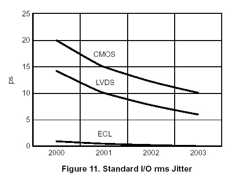
> From ONSEMI TND301 appl. note
Well found. 😉
> Will the jitter be reduced with parallel devices ?
In theory when the error is random it will reduce with parallel devices. The questions is in this case however not how much jitter, but how well matched are the devices in propagation delay tolerances (usually +/-80ps or so). And since they are all voltage output, you end up smearing the rising edge of the signal over 80ps as signals from different paralleled devices arrive asynchronously. Not really clever, it is ?
Patrick
OK 5.50 at Digikey. You can still afford. 😉
> Did you see the EP series ? Works from 5 V and 3,3 V. Flipflop and buffer are faster than EL series, have jitter specified = 0,2 ps.
Yes, and I have ordered EP whereever I can. But they don't have everything that I need in EP.
> From ONSEMI TND301 appl. note
Well found. 😉
> Will the jitter be reduced with parallel devices ?
In theory when the error is random it will reduce with parallel devices. The questions is in this case however not how much jitter, but how well matched are the devices in propagation delay tolerances (usually +/-80ps or so). And since they are all voltage output, you end up smearing the rising edge of the signal over 80ps as signals from different paralleled devices arrive asynchronously. Not really clever, it is ?
Patrick
In theory when the error is random it will reduce with parallel devices. The questions is in this case however not how much jitter, but how well matched are the devices in propagation delay tolerances (usually +/-80ps or so). And since they are all voltage output, you end up smearing the rising edge of the signal over 80ps as signals from different paralleled devices arrive asynchronously. Not really clever, it is ?
I wonder what happens with my 16 DACs per channel switching at the same time...
Well, for the D to A conversion process, maybe you DO want some smearing ?? 😉
I'll think about this when I have time (not tonight), but I am using 4x PCM1704 in diff mode, so I do not really have that problem (if it is one).
Patrick
I'll think about this when I have time (not tonight), but I am using 4x PCM1704 in diff mode, so I do not really have that problem (if it is one).
Patrick
At least for the ECL you have a lower output impedance into the same load.
I'm waiting for a 10 ps / 16 bit sampling plug-in now for years and it just doesn't show up on ebay...
I'm waiting for a 10 ps / 16 bit sampling plug-in now for years and it just doesn't show up on ebay...
Have things to sort out tonight. Till tomorrow.
Take a look at the IV stuff I sent you per PM.
Patrick
Take a look at the IV stuff I sent you per PM.
Patrick
I'll think about this when I have time (not tonight), but I am using 4x PCM1704 in diff mode, so I do not really have that problem (if it is one).
I think it is not trivial...
PCM1704 balanced is also two DACs switching at the same time.
- Status
- Not open for further replies.
- Home
- Source & Line
- Digital Source
- differential clock