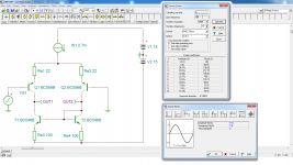
I have try to simulate Differential Input Stage in TINA 9.3 software and when i simulate using long tail resistors (7.2k resistor on both collectors of Q1&Q2) i im getting THD at 0,0023569%), then i use improved version using current mirrors and i im getting this THD witch is 4,1958%..i im reading bof by dr douglas self and he mention that current mirror improves linearity.
How to fix this in simulation? I im trying for hours to find where i made error but not to go...in LT Spice i im getting with current mirror the same high THD.
Any help welcome.
How to fix this in simulation? I im trying for hours to find where i made error but not to go...in LT Spice i im getting with current mirror the same high THD.
Any help welcome.
Attachments
Generally when you are dealing with ltp measurements it is in a complete circuit with closed loop feedback. Add a vas stage with a feedback loop, then change things in the ltp to see the effects.
Your problem is that you simply do not understand what the circuit is doing or is supposed to do.
What do you expect on output (2)? Is this voltage going to have any sense as you are actually feeding current into a transistor connected as a diode?
What is the load the left side sees on the collector of the LTP? You are comparing this with a resistor of 7.2k - what is the 'resistance' of the current mirror? And - what determines the quiescent (no signal) voltage on the collector of the lefthand LTP transistor?
Simply put: you are using a simulator. With simulators, this simple rule always applies: Garbage in = garbage out. Before measuring distortion, have you checked if the voltages on the terminals of the transistors actually make sense, and make the transistor work in it's normal operating area? When simulating a circuit you still have to know exactly HOW it works (the simulator only tells you 'how much'), or you will not know where to look for what and how to interpret the results.
- Status
- Not open for further replies.