Hi all...I have been posting at the tubes section about converting what I suspect is a ne5532 used as a differential amp..into a tube differential amp..
Can anyone confirm that it is a differential configuration..or better even post or mail me a schematic of said cdplayer?..
Cheers,
Bas
Can anyone confirm that it is a differential configuration..or better even post or mail me a schematic of said cdplayer?..
Cheers,
Bas
Hi Bas,
Many of japanese low-fi (or mid-fi) CDP uses NE5532 for the OP-Amp. The higher levels usually use OPA.
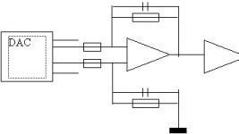
These CDPs have the same circuit topology. Right after the Digital To Analog converter, you will found the OP-amp, after the OP-amp there are 2 transistors configured almost similar like differential pairs. These transistors are for muting purposes (to avoid unwanted pop during turn on and off, in place of a relay for expensive CDPs). Removing these transistors will improve the sound performance.
May be this is what you were talking about?
Many of japanese low-fi (or mid-fi) CDP uses NE5532 for the OP-Amp. The higher levels usually use OPA.
These CDPs have the same circuit topology. Right after the Digital To Analog converter, you will found the OP-amp, after the OP-amp there are 2 transistors configured almost similar like differential pairs. These transistors are for muting purposes (to avoid unwanted pop during turn on and off, in place of a relay for expensive CDPs). Removing these transistors will improve the sound performance.
May be this is what you were talking about?
OK, I’ve skimmed your thread on tube forum.
I noticed that you want to replace the amplifier section of your CDP with a tube (PF86).
I’m not an expert, so I will not try to answer your question regarding how to implement the upgrade. Rather, I will comment and give my opinion on your post.
I think there had been a mis-analogy between OP-amp circuit and tube circuit or whatsoever (grid stopper, differential, balanced terms). As far as I can remember, NE 5532 is a dual (gain stage) OP-amp with 8 pins. 2 pins for power supply, 3 pins for each gain stage. In each gain stage, 1 pin is the output, 2 pins are the input, of which 1 is reffered to ground (depend on the phase invertion wanted) and 1 for incoming signal.
I think what you saw as 19K9 on pin 2 and 3 are the resistors connecting each stage’s input to ground.
If you want to replace the OP-amp with a tube amplification, that will be a total upgrade! Then, why you have to be bothered with the OP-amp circuit? To me, this is just like creating a new amplifier (you may want to arrange your tube in a single ended arrangement)
Personally, I don’t think that replacing an OP-amp with a single tube is an easy task, unless improvement is not a necessary constraint. But you can ask for other's work and do a "plug and play" with a little modification.
Hi Jay,
Yep, I think that is what is happening. That is a differential amp right? If so I should be able to build a tube version for it.
Thanks.
Regards,
Bas
Yep, I think that is what is happening. That is a differential amp right? If so I should be able to build a tube version for it.
Thanks.
Regards,
Bas
Yes, the circuit is a diferential amplifier, although I'm not so sure what is the real function of the differential amplifier here (I only know feedback and "vocal cutting" implementation).
I have modified my CDP only starting from the OP-amp, so I don't know what the DAC really do with the input signal. But I have seen in the net (I have tried to find it again with no success) the modification with a tube so you are right that you can do it. But, whether you HAVE TO build a differential amp also (with the tube), that is what I don't understand. I seen only 1 tube (in the picture, not in the schematic), may be it was a dual triode.
Regards,
Jay
Jay said:Yes, the circuit is a diferential amplifier, although I'm not so sure what is the real function of the differential amplifier here (I only know feedback and "vocal cutting" implementation).
I have modified my CDP only starting from the OP-amp, so I don't know what the DAC really do with the input signal. But I have seen in the net (I have tried to find it again with no success) the modification with a tube so you are right that you can do it. But, whether you HAVE TO build a differential amp also (with the tube), that is what I don't understand. I seen only 1 tube (in the picture, not in the schematic), may be it was a dual triode.
As you have a differential output from the DAC, you will need a differential circuit. Have a look at Thorsten's site:
http://thunderstoneaudio.nav.to/
And look for:
Thermionic Valve Analogue Stages for Digital Audio
There he explains how to proceed with DACs having differential outputs and provides a tube circuit.
Carlos
- Status
- Not open for further replies.
- Home
- Amplifiers
- Solid State
- Differential amp in the Sony CDP-911.