I have 2 of these amps and 1 is working. I am pretty sure that t got the voltages correct here as well as the ground connections.
I have plugged it in and have heard a reassuring pop from the speaker but no 1Khz tone will play. I have taken various voltage readings at the lm3886 pins but I don't know what to compare them to.
V+ = 31
V- = 31-
Pins:
1=31+
3=31-
5=31+
10=-14
9=31-
I don't know what I am doing and how to figure out which part or parts are bad is a mystery to me.
This board is one that had started smoking earlier and I replaced the lm3886, 2 ceramic capacitors, and 2 electrolytics. Perhaps I didn't get all the faulty parts.
So, how do I proceed ? Try and salvage these parts and have another go at another circuit board ?
Or something else?

Thanks
I have plugged it in and have heard a reassuring pop from the speaker but no 1Khz tone will play. I have taken various voltage readings at the lm3886 pins but I don't know what to compare them to.
V+ = 31
V- = 31-
Pins:
1=31+
3=31-
5=31+
10=-14
9=31-
I don't know what I am doing and how to figure out which part or parts are bad is a mystery to me.
This board is one that had started smoking earlier and I replaced the lm3886, 2 ceramic capacitors, and 2 electrolytics. Perhaps I didn't get all the faulty parts.
So, how do I proceed ? Try and salvage these parts and have another go at another circuit board ?
Or something else?
Thanks
-31v on pin 3 shows a major problem because this is the speaker output and so should be at zero volts. Your speaker may have been fried.
Pin 10 (an input) should be at zero volts at all times as it should only ever be ground referenced. I would look there first.
How to proceed... the LM3886 MUST be attached to a heatsink at all times. Also use a bulb tester to limit current during testing (a very small 40w or less would be ideal).
Edit... and never have the speaker connected during initial testing.
Well. The good news is that the layout could be half-decent. It also looks like the vendor has fitted all of the necessary decoupling caps: Large bulk cap, medium electrolytic, small ceramic. Also, the not-so-optional stability components are there. Excellent! That's unusual for the various eBay vendors.
I disagree on the choice of the Zobel network (4 Ω + 220 nF) and the use of a fancy cap for the Zobel as it doesn't participate in the audio spectrum, but that's not the cause of your trouble. Also, the Zobel resistor should be a 2 W type. Yours looks more like a 0.5 W.
I'm concerned that the polarity markings of the electrolytic caps on the supply are pointing away from each other. Are you sure they're installed correctly?
If you're having -14 V on pin 10 (non-inverting input) and -31 V on pin 9 (inverting input), the output should be positive. You're reporting -31 V on the output (pin 3), so something's broken there. Is the input to the amp floating by any chance? There should be a resistor from pin 10 to ground on the 'inside' of the large film cap.
The smoke you let out earlier is not likely to be caused by the LM3886 itself. It has a built-in thermal protection that'll shut the IC down when the internal temperature exceeds 155 ºC.
You can run the LM3886 without a heat sink for a short time as long as you do not have a load connected. I do that quite a bit for quick tests. The IC will get hot, but it'll produce a rail-to-rail sine wave just fine ... as long as you do not have a load connected.
To operate the LM3886 with a load, you do need a heat sink. You can see my page on the topic here: Taming the LM3886 - Thermal Design. With the metal back LM3886, you also need the appropriate shoulder washer on the mounting screw and a thermal pad between the LM3886 and the heat sink to avoid shorting VEE/V- to the heat sink.
Tom
Last edited:
Wow, a lot to look for.
I have been measuring voltages at various points and thought to test the zener.
It's a 16v 3W 5%.
It measures 40 ohms in both directions, so it sounds like it's bad.
I have a lot of zeners laying around but not like that so it's on order.
I think that I will try it with one of mine and see what happens.
Well, I have been testing it with a speaker and without a heat sink. Maybe I have been lucky.
Also, when this thing is working properly, what will the output signal look like ?
Could I see it with a multi meter ?
You could verify DC offset levels on the output at least. Should be <+/-100 mV or thereabouts.Also, when this thing is working properly, what will the output signal look like ?
Could I see it with a multi meter ?
You could also look for two matching electrolytics of at least a few hundred µF at maybe 50 V or greater, connect these back-to-back (the DIY option for making a bipolar cap), and then use that in series with your test speaker. It would be protected even if there is DC on the output.
The zener appears to be in the mute circuit see diagram here A Complete Guide to Design and Build a Hi-Fi LM3886 Amplifier - Circuit Basics
")
I have been testing it with a speaker and without a heat sink. Maybe I have been lucky.
Very lucky if no damage. It's not good to do initial testing of a power amplifier on a speaker.
Always use a dummy load like an 8 ohm power resistor, and a scope to see the output waveform.
A minimal scope is very low cost these days (even less than $100) and is essential. They often
include a built-in basic function generator, like this one.
PicoScope 2204A-D2 10MHz 2-Ch Oscilloscope w/out Probes (PP917) ($115.00) : Saelig Online Store
Last edited:
I have been measuring voltages at various points and thought to test the zener.
It's a 16v 3W 5%.
It measures 40 ohms in both directions, so it sounds like it's bad.
Not necessarily. Did you measure it while it was still in the circuit? That could be why.
When the amp is powered up do you get about 16 V across the zener? Is it connected to the mute pin (pin 8) by any chance? A 3 W zener is a rather beefy zener for the mute circuit (draws 0.5-1 mA).
I have a lot of zeners laying around but not like that so it's on order.
I think that I will try it with one of mine and see what happens.
Also, when this thing is working properly, what will the output signal look like ?
Could I see it with a multi meter ?
The output should look like an amplified version of the input. So if you apply a sine wave on the input, you should get a sine wave on the output. You can generate a test tone at wavtones: Professional Online Audio Frequency Signal Generator
Make yourself a 400 Hz test tone, 5 seconds in length, at -6 dBFS. Play it on repeat using your favourite media player. Adjust the input voltage to 100 mV RMS using the volume control of the media player. You should have 2.0 V RMS on the output (assuming 26 dB = 20x gain). I choose 400 Hz because most meters can measure this.
What does the Zener do ?
It's hard to tell without a schematic. I'm guessing it's part of the mute circuit and intended to shut off the amp once the supply voltage drops below the zener voltage.
Tom
It's hard to tell without a schematic. I'm guessing it's part of the mute circuit and intended to shut off the amp once the supply voltage drops below the zener voltage.
Schematic appears to be here:
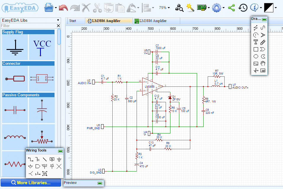
Or:
EasyEDA - A Simple and Powerful Electronic Circuit Design Tool
Last edited:
Thanks Bone
So looking at the circuit there would be insufficient current available to damage the Zener as long as the 100uF was OK and not fitted incorrectly.
Before i try anything more, I will try and put a dummy load, like an 8ohm resistor in lieu of the speaker. I might try that back to back dual capacitors if I can figure it out.
So, given that the zener is faulty does that mean the 100uf caused it ?
Re how to measure the output, in my inexperience, there is AC and DC. Since I was expecting to see a sine curve, and a sine curve sorta looks like AC but no joy. I don't know what DC offset is so I will read up on it.
I do have a scope, it's an older analog beast that I think works.
I had a thought to try this to see if it would help.
I have an identical amp that works so I could measure it's voltages at various points as a reference.
Big question. There is a contact on the board labeled "Earth". My inexperience told me that it was to be connected to the middle prong from the mains.
I tried that a couple times and it lead to much smoke, a small fire, and me swearing off of the hobby. I think that in the final wiring scheme, all the pcb gnd, and the earth, come together to a chassis screw. Well since I am testing these bits separately and outside the case I don't know what to do with "Earth" and the middle prong from the mains. For now they are not connected and I think that I will leave them like that unless I hear different from you.
Phew!
Assuming the schematic in post 13 is correct... is your SIG_GND connected to your PWR_GND somewhere? It needs to be... if your signal ground is floating that will give you your DC on the output...
Yes it is.
Before i try anything more, I will try and put a dummy load, like an 8ohm resistor in lieu of the speaker. I might try that back to back dual capacitors if I can figure it out.
So, given that the zener is faulty does that mean the 100uf caused it ?
Re how to measure the output, in my inexperience, there is AC and DC. Since I was expecting to see a sine curve, and a sine curve sorta looks like AC but no joy. I don't know what DC offset is so I will read up on it.
I do have a scope, it's an older analog beast that I think works.
I had a thought to try this to see if it would help.
I have an identical amp that works so I could measure it's voltages at various points as a reference.
Big question. There is a contact on the board labeled "Earth". My inexperience told me that it was to be connected to the middle prong from the mains.
I tried that a couple times and it lead to much smoke, a small fire, and me swearing off of the hobby. I think that in the final wiring scheme, all the pcb gnd, and the earth, come together to a chassis screw. Well since I am testing these bits separately and outside the case I don't know what to do with "Earth" and the middle prong from the mains. For now they are not connected and I think that I will leave them like that unless I hear different from you.
Phew!
An 8 ohm dummy load would draw just as much current as a speaker. Fault find with NO load attached.
If (and read what tomchr said first about it being in circuit) the Zener is faulty then yes, it means the 100uF caused it. That would only be possible however if the chip had allowed significant current to flow from the mute pin (faulty chip) AND the cap ended up reverse biased.
So at this stage its unlikely and the Zener may well be OK.
DC offset is any DC voltage appearing at the amplifier output. It should be lower than a say -/+50 millivolts for this circuit. Any voltage you measure here would appear across the speaker which is not good and why we test with NO load attached.
Nothing on the PCB has to be connected to mains earth... that's a totally different question and unrelated to the fault. What is important is that the zero volt line of your power supply connects to the correct point/s on your PCB.
Here is a link to the original project.A G
Ëarth, on the Power board, connects to the chassis via a Ground Loop Breaker. Chassis connects to PE (mains ground). The amp will work fine without these connections.
Ëarth, on the Power board, connects to the chassis via a Ground Loop Breaker. Chassis connects to PE (mains ground). The amp will work fine without these connections.
Last edited:
I apologize but I forgot to mention that the zener was tested out of the circuit. What I had read about that was it should read high resistance in one direction, and lower in the other. It didn't. It ready 40ohms in both directions. I tried the test on some zener that I had laying about and they followed the quoted pattern. 57meg ohm vs 26meg ohms. Hence my conclusion that the zener is faulty.An 8 ohm dummy load would draw just as much current as a speaker. Fault find with NO load attached.
If (and read what tomchr said first about it being in circuit) the Zener is faulty then yes, it means the 100uF caused it. That would only be possible however if the chip had allowed significant current to flow from the mute pin (faulty chip) AND the cap ended up reverse biased.
So at this stage its unlikely and the Zener may well be OK.
DC offset is any DC voltage appearing at the amplifier output. It should be lower than a say -/+50 millivolts for this circuit. Any voltage you measure here would appear across the speaker which is not good and why we test with NO load attached.
Nothing on the PCB has to be connected to mains earth... that's a totally different question and unrelated to the fault. What is important is that the zero volt line of your power supply connects to the correct point/s on your PCB.
The caps are wired properly but I will check again.
- Status
- This old topic is closed. If you want to reopen this topic, contact a moderator using the "Report Post" button.
- Home
- Amplifiers
- Chip Amps
- Different amp same trouble. Lm3886 can't get working