That is new... a cap in series with the GND resistor... can you suggest a good reading so I can grasp the idea. I am used to parallel caps in the source resistors to degenerate DC but tthis is different. Should I place the cap directly to GND before or after the 3k9 resistor ?
I found this, look at page 77 (of 94) which might help explain things.
http://www.ti.com/lit/an/sboa092a/sboa092a.pdf
The cap should be placed in the earthy end of the network simply because it is physically a larger part and so more prone to pick up any noise/hash. Electrically it doesn't matter as it's a series network.
You mentioned "caps across feedback resistors".
http://www.diyaudio.com/forums/anal...u-have-checked-see-its-stable-havent-you.html
Have fun...
Just in case 🙂
It shouldn't need it if the layout is good but won't do any harm if you want to add it.
It shouldn't need it if the layout is good but won't do any harm if you want to add it.
I have about 20 Texas Instruments 5532P ones in the stash. Are they any good for offset and noise? Anybody tried those? I remember my old Signetics stamped ones were quieter and had much better offset than ST I could find everywhere in shops.
Hi Mooly
In the TI pdf page 16 I read "The feedback resistor is of particular importance if the op amp selected is a current-feedback type. The stability of current-feedback op amps is dependent entirely on the value of feedback resistor selected, and the designer should use the value recommended on the data sheet for the device."
How can I determine if a particular opamp is a current-feedback type ?
Ricardo, connect it as a follower with output connected to pin 2. If it is a current feedback amp it will oscillate and likely get very hot. A resistor in that position between 1 - 3kOhm would then cure the problem. On the other hand you could simply look up the spec sheet.
99% of the opamps on this forum are VF (voltage feedback).
More reading...
http://www.ti.com/lit/an/slva051/slva051.pdf
More reading...
http://www.ti.com/lit/an/slva051/slva051.pdf
Perfect 🙂
Thank you both !
Just another question. I see it is much more common to find inverting amplifiers than non inverting. Why is that ?
Non inverting have higher input impedance (and it does not vary).
In the case of a non inverting simple amp, how can I determine the best value for the feedback resistor. I am confused because the current there should be zero or negligible.
Last edited:
Hmmm... I would have said non inverting were more common. Your Denon buffer is non inverting and will be when the extra parts are added.
Inverting configuration though is thought by some (me included) to offer better performance. See post #2 here,
http://www.diyaudio.com/forums/soli...fet-amplifier-designed-music.html#post1452488
There are only two resistors used per opamp. In the above example that's R1 and R2 for the first stage and R3 and R4 for the second.
Gain is just -R2/R1 (minus denotes inverting) and -R4/R3. The 22pf caps were added to optimise square wave response (not needed for stability).
R1 sets the input impedance of the first stage and R3 the input impedance of the second. That's a figure you have to decide but 18 k is sensible value for modern source equipment. Tha gain required is then set by choosing suitable feedback resistor.
So if R1 were 1k and R2 100K the voltage gain would be 100 (very high) and the input impedance low at 1k. Easy 🙂
Non inverting... the input impedance is set by the value of "resistance" from the non inverting input to ground. So if you had a 10k to ground from the non inverting input that would set the input impedance. That assumes the input is AC coupled.
The two resistors in the feedback network, call them RF and R2... RF goes from opamp output to the inverting input and R2 from inverting input to ground via that electrolytic cap 🙂
If you use a bjt or bipolar input type opamp like the NE5532 then it's good practice to keep RF and the input resistor the same to ensure equal DC bias currents flow into each input. Not doing so can cause large DC offsets at the opamp output.
Use a FET opamp and that problem is totally eliminated.
The gain of the non inverting amp is (RF+R2)/R2 so for a gain of 10 you would need a 9k feedback resistor and a 1k for R2. The electrolytic cap ensures that the gain falls to 1 at DC.
I have about 20 Texas Instruments 5532P ones in the stash. Are they any good for offset and noise? Anybody tried those? I remember my old Signetics stamped ones were quieter and had much better offset than ST I could find everywhere in shops.
Hi Salas... I dunno is the answer to that one. Many folk only rate the original Philips/Signetics branded ones.
Thank you Mooly
So there is no rule of thumb to determine the optimum values.
It all depends on the input impedance we need to get.
I find this very important also "If you use a bjt or bipolar input type opamp like the NE5532 then it's good practice to keep RF and the input resistor the same to ensure equal DC bias currents flow into each input. Not doing so can cause large DC offsets at the opamp output."
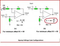
In the following pic, what do you mean by input resistor in the non inverting layout ?
So there is no rule of thumb to determine the optimum values.
It all depends on the input impedance we need to get.
I find this very important also "If you use a bjt or bipolar input type opamp like the NE5532 then it's good practice to keep RF and the input resistor the same to ensure equal DC bias currents flow into each input. Not doing so can cause large DC offsets at the opamp output."
In the following pic, what do you mean by input resistor in the non inverting layout ?
Attachments
I've mentioned this before. but the TI NE5532/5534 are POS and nothing like the Philips/Signetics/Raytheon parts. I proved it with a 5534 design that would not work at all with TI parts. I contacted TI to discuss and they said "the part is equivalent, meets the published specs" but with different internals. The TI5532 is really noisy and grainy sounding, I almost got kicked out of a recording studio after doing repairs using them.
Off from the parts bin to the dust bin then. What is better nowadays? Is that Philips Thailand one I see on Epay anyhing good & original?
Thank you Mooly
So there is no rule of thumb to determine the optimum values.
It all depends on the input impedance we need to get.
I find this very important also "If you use a bjt or bipolar input type opamp like the NE5532 then it's good practice to keep RF and the input resistor the same to ensure equal DC bias currents flow into each input. Not doing so can cause large DC offsets at the opamp output."
In the following pic, what do you mean by input resistor in the non inverting layout ?
Look at this. I've added a cap to the non inverting amps feedback network (normal practice) and it makes this easier to understand.
This is how it works...
Bjt opamps have a small DC current that flows into or out of the two inputs all the time. It's tiny but not negligable and if you look on a data sheet it's called the "input bias current". The 5532 is quoted as 200 to 800 nano amps.
Seems to small to bother about ? What happens is this. That tiny curent develops a voltage across the resistors connected to the opamp inputs. Look at R1 in your first diagram. Suppose that were 470K. 800na develops 0.376 volts across that. Not so insignificant now. That DC voltage appears as an "input" to the opamp and is now the cause of a DC offset voltage that appears at the output.
The same issue appears at the other opamp input. Whatever resistance is connected there also develops a volt drop that is seen by that terminal as an "input" voltage.
So we go back to basic opamp theory that says that the opamp output will do whatever is required to keep the voltage difference between the two inputs at zero. And what we have to do is keep our "input offset" voltages equal. We do that by ensuring that each input sees the same resistance, and that means that the voltage developed is equal too at each input thus minimising the error.
So your first non inverting example.
By AC coupling the feedback return we only have to keep R1 and RF the same. If the network wasn't AC coupled then we would have to figure the combined effect of RF and R.
In the inverting example we add a resistor in series with the non inverting input as shown. The value is equal to RF. That develops a volt drop as we have shown that equals the error at the inverting input.
The downside to that is that the resistor add noise (that is negligable) but more importantly it makes the input pin sensitive to stray pickup so carefull layout is essential. Or the resistor can be bypassed with a cap to effectively "ground" the pin at AC.
If we use a FET opamp all these problems dissapear because the FET opamp has essentially zero DC bias current. No current = no volt drop acrosss input resistanaces.
Attachments
The test results from Elektor labs stemming from the Douglas Self 5532 amp haven't made it into this thread?
Your welcome...
For experimenting the TLO72 (dual) and TLO71 (single) are good. Sonically they can better the 5532 as long as the output loading isn't to severe. Old they may be but they are pretty decent performers.
Better than that and your looking at the likes of the OPA2604 (OPA604 single) and the OPA2134 (OPA134 single).
Looking at the datasheets, the OPA134 might be a very good contender.
Now I must choose between non inverting / inverting.
Severall opinions suggest that inverting layouts sound better... but why ?
And if I use only one stage (switch + pot + opamp) to build a preamp, what should I be aware of regarding inverting/noninverting signals ?
Is inverting signals audible ?
Now I must choose between non inverting / inverting.
Severall opinions suggest that inverting layouts sound better... but why ?
And if I use only one stage (switch + pot + opamp) to build a preamp, what should I be aware of regarding inverting/noninverting signals ?
Is inverting signals audible ?
- Status
- Not open for further replies.
- Home
- Design & Build
- Parts
- Difference between NE5532P and NE5532AN