Hey guys, can someome please explain me the diference between use an transformer with 2 diferents outputs and with 1 output? i mean, i want to know wich is the diference rectifing using 4 and 8 diodes.
Regards
Regards
🙂
But some diference in performance?
will be better use an transformer of 24-0-24 instead 0-24v?
will be better use 8 diodes instead 4?
But some diference in performance?
will be better use an transformer of 24-0-24 instead 0-24v?
will be better use 8 diodes instead 4?
with 24-0-24 you can get +/- 35volts DC with 4 or 8 diodes.
with 24-0-24 you can get + 35 volts dc with 2 diodes or -35VDC with 2 diodes not at the same time.
with 0-24 you can only get +35VDC or -35VDC but not both at the same time with 1 diode or 4 diodes
some people like to use 4 diodes with a center tap transformer like you have 24-0-24 to get + 35 and -35 for both channels of an amplifier. Some people like to use 4 diodes for the +35vdc and 4 diodes for the -35vdc.
some people would use 16 diodes for a stereo amplifier.
There can be less interfearence between channels if you use 2 bridge rectifiers ie 8 diodes. Same with using 2 or 4 transformers instead of one transformer.
some people may use 1 transformer and 4 diodes for the +35vdc on one channel
and then use a 2nd transformer and 4 more for the -35vdc on the same channel.
Then use 2 more transformers for the other channel.
some people put the power supplies in an external chasis to prevent interfearence /hum
or you can use one transformer and 4 diodes for everything including the power amp preamp, dac, cd player all in one chasis. Its up to you.
A bridge rectifier makes more efficient use of the transformer secondary, so you can either have a cooler transformer or more current. Silicon rectifiers have low voltage drop and are cheap so a bridge is efficient.
For valve rectifiers the centre-tapped secondary is more common. Two valve rectifiers in series (as in a bridge) would drop a lot of voltage, and most rectifiers come in common cathode. You can have a hybrid bridge - valves on top, silicon to ground.
For valve rectifiers the centre-tapped secondary is more common. Two valve rectifiers in series (as in a bridge) would drop a lot of voltage, and most rectifiers come in common cathode. You can have a hybrid bridge - valves on top, silicon to ground.
can someone point me to same PSU design (schematic) using 4 or 8 diodes? i want to see the diference in the screen 🙂 i will build both configuration and will test for some audible diference
can someone point me to same PSU design (schematic) using 4 or 8 diodes? i want to see the diference in the screen 🙂 i will build both configuration and will test for some audible diference
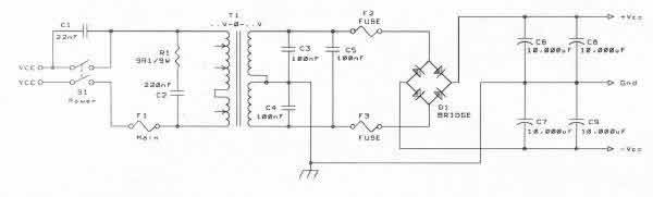
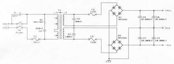
On this schematic
which is the advantage or disavantage if put the fuses (F2 and F3) after C8 and C9?
which is the advantage or disavantage if put the fuses (F2 and F3) after C8 and C9?
In the second schematic in post #7, it would be better if central ground was not at the location shown in the schematic, and no sooner than the GND arrow on the right side of the schematic. This would prevent the central ground from being influenced by capacitor charging currents (ripple). In fact, why not keep the plus and minus capacitor grounds separate up to a central ground on the right side of the schematic? Have each capacitor charging current returned in its own local loop, and keep the ground reference point out of this loop. Otherwise, the benefit of the double bridge is reduced.
Likewise, the central ground in the first schematic should be on the right side.
Likewise, the central ground in the first schematic should be on the right side.
Fuses protect the things near them in the circuit. As shown, they protect the transformer from shorted diodes or shorted capacitors (less likely). Moving them to after the capacitors protects the diodes from amplifier faults, but may introduce some bass distortion.which is the advantage or disavantage if put the fuses (F2 and F3) after C8 and C9?
- Status
- Not open for further replies.
- Home
- Design & Build
- Construction Tips
- Diferences between use 4 or 8 diodes in PSU