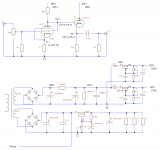
Attached is the as-built schematic. Measured voltages are in brackets. It sounds very good and in general I'm happy with it.
But sometimes it becomes unstable. It makes a loud, low-frequency motor-boat-ish type of sound that's a huge problem if I have a solid-state amplifier hooked up. In fact it blew a fuse in my amp the first time it happened.
All but 1 time this instability occurred after turn-on, and only if the preamp had been on recently. After the motorboat noise lets up I'm left with very, very low gain. I think what's happening is the LR8 that controls the 300V supply goes into its protection mode, reducing its output to around 80V. I saw it happen a couple of times on the bench, but I can't tell you definitively if this behavior is related to the motorboat.
1 time this happened while the preamp was in use. It had been on for half a day, just playing the radio and sounding good, when all of a sudden it went into this instability with no warning. At that time the power supply resistor values were a little different so that there were considerably higher voltages across both LR8s. I think the 300V LR8 in particular had 350V on its input side. Since the LR8s current capacity is dependent on the voltage difference across it, I'm guessing it went over and switched into the safety mode. But, again, I can't confirm this.
Is there anything in this schematic that looks like trouble? Is it typical for the LR8 to need a substantial amount of time to reset before you can turn it back on?
Attachments
It may not be low frequency oscillation but rail to rail ultrasonic oscillation which manifests its as a "motor boating" type sound. That would cause excessive current draw and the LR8 may be going into thermal shutdown. It would then need some time to cool down before it starts working again.
Where would the ultrasonic oscillation come from ??? - that 6CG7 cathode follower
needs a grid stop resistor.
Cheers,
Ian
Where would the ultrasonic oscillation come from ??? - that 6CG7 cathode follower
needs a grid stop resistor.
Cheers,
Ian
You want to use a high voltage power transistor with the lr8, sort of like you would if you were to try and get more current while using a lm317. It's easier for me to post the link than to describe what you will need to do........
OTB - A Solid-State Filter Choke or Field Coil Replacement
I use the same setup in my regulators for preamp and phono-pre and have no issues. You can also get TO92 heat sinks. This may help some, but you really need to use a power transistor as well. I use a horizontal output transistor. High power and pretty cheap to buy.
A single N channel mostfet fed by a reference voltage, derived from a zener diode wil work just fine.
V4lve.
V4lve.
Thanks very much for the tips. I really appreciate the help.
The 265V side draws about 5-6 mA and I don't think I've ever seen it go into shutdown. So I think I'll leave it as-is.
The 300V side draws about 10-11 mA, which I guess is really riding the edge of what the LR8 can do. Adding the TIP50 and a diode is only 2 extra parts for a lot more current capacity, so it seems worth doing. I'll try that out and see what happens. I think I actually have a TIP50 around here somewhere.
As for a grid-stopper resistor, I kind of thought that might be something I needed but I haven't been able to find a clear answer on that. I also haven't been able to find a method for selecting a proper grid-stopper resistor value. Does anyone know of a resource where I could learn how to select a value? Or if it's simple enough, could you explain it?
The LR8 can handle about 0.3W so you may be on the edge of the SOA.
The cathode resistor should be bi-passed -- or use a Red LED.
The cathode resistor should be bi-passed -- or use a Red LED.
Or an LR8? I have some IRF840's on hand, would that be useful?A single N channel mostfet fed by a reference voltage, derived from a zener diode wil work just fine.
Why is that?The cathode resistor should be bi-passed
Yes, you can use an IRF840 if you want. I have never done it that way, but here is a link to something similar using that part.....
High and Low Voltage Feedforward Shunt Regulators
I would change it up a bit to use it as a pass through device and have the lr8 drive the gate so that you could make it an adjustable supply. I would have to breadboard it to see for sure since I haven't used a mosfet in that way before, but it seems that it would work. Could be interesting. Just remember that whatever you use as your pass device that you heat sink it.
It would, but it wouldn't be adjustable. That is the beauty of the LR8.
You could simply put a potentiometer and a resistor in series. parallel to the zener diode. and feed the gate from the potentiometer wiper.
v4lve.
Why is that?
The cathode likes to be at a.c. ground potential. When you bypass the resistor, however, you form a filter and you have to use a sufficiently large value to not limit the low frequency response. 1K//22uF has an f3 of 7.2Hz
A LED solves this problem in most respects, but you only have a choice of discrete values. See SY's article on "The Red Light District" on his website.
You should rather check voltages at turn-on. At turn on the grid of CF (6CG7) is at 265V potential until Ia of EF86 is settled. Reverse connected diode(s) will protect from exceeding grid-to-cathode voltage at transition. Next thing - consider screen grid resistor for EF86.
See this thread:
http://www.diyaudio.com/forums/tubes-valves/200072-dc-coupled-cathode-follower-driving-me-nuts.html
See this thread:
http://www.diyaudio.com/forums/tubes-valves/200072-dc-coupled-cathode-follower-driving-me-nuts.html
I added a transistor as a pass element in the 300V regulator section and it seems to have solved the problem. I have not been able to get the LR8 to go into protection mode and I have not been able to reproduce the weird oscillations I was hearing. Thanks very much for everyone's help.
- Status
- Not open for further replies.
- Home
- Amplifiers
- Tubes / Valves
- Did I use the LR8 in this EF86 preamp correctly?