A couple more notes, the layout is revision 1.2, but it is still based on the 1.1 schematic.
The bias can be adjusted via the pot, but if you wish to you can change the values of R16/R17 to get a bit more bias with less current through the VAS.
Cheers!
Russ
The bias can be adjusted via the pot, but if you wish to you can change the values of R16/R17 to get a bit more bias with less current through the VAS.
Cheers!
Russ
Russ White said:Just about any PCB manufacturer will clip the silk around the pads. MrMajestic, make sure you ask them to do this if you want it. Even if the silk were not clipped, all the components can be soldered from the bottom where there is no silk.
I will ask Olimex about it, thanks.
A hint Russ:
It is a good idea to have the same revision on the pcb as in the schematic or at least write in the schematic which pcb layout that fits. I work at Ericsson and they have a revision system that is "a bit" over yours
Think this: I'll pick up a pcb of your and want to grab the corresponding schematic without any hesitation.
peranders said:A hint Russ:
It is a good idea to have the same revision on the pcb as in the schematic or at least write in the schematic which pcb layout that fits. I work at Ericsson and they have a revision system that is "a bit" over yours
Think this: I'll pick up a pcb of your and want to grab the corresponding schematic without any hesitation.
Hah P.A. you are so hard to please. 😉
Keep in mind this board was done just as a favor not a production thing for me. 🙂
Still if this makes you feel better:
gerbers
Now it should be clear it is the 1.1 circuit and REV 1 of the double side DIY layout.
Cheers!
Russ
I'm not particulary displeased but I see a potential problem mainly for you, getting unnecessary questions.Russ White said:Hah P.A. you are so hard to please. 😉
Compare this: A project here lacks of a reference wiring schematic/picture. How many questions have we got about hum and offset problems? What would happen if this project had in the manual with clear instructions about this? I'm sure you all know what project I mean.
Just sent the files over to Olimex. Hopefully they will find them useable 🙂 This is just a test run, so the boards will be more expensive than a bigger run. Its just 6 boards in total so holler if you are interested.
Just got my order form back from Olimex. Going to send payment tomorrow and hopefully the boards will turn out nice. If anyone want to try out the first run, the boards will be 15€ each plus shipping.
MrMajestic,
How is the project going?
Just wanted to check in and see if I can help out in any way.
Cheers!
Russ
How is the project going?
Just wanted to check in and see if I can help out in any way.
Cheers!
Russ
Russ White said:MrMajestic,
How is the project going?
Just wanted to check in and see if I can help out in any way.
Cheers!
Russ
Im still waiting for Olimex to deliver the boards. I knew I should have paid up for better shipping 🙂
Thanks for you support.
Guess what showed up in the mail today 🙂
An externally hosted image should be here but it was not working when we last tested it.
An externally hosted image should be here but it was not working when we last tested it.
Russ White said:Excellent! They look very good. Let the fun begin. 🙂
Cheers!
Russ
Ok, Im about to attempt buidling two of these suckers now. A few questions though. Do you think that a 15VA transformer is enough for 2 channels? Also, what diameter of magnet wire did you use for R26?
Ok, Im about to attempt buidling two of these suckers now. A few questions though. Do you think that a 15VA transformer is enough for 2 channels? Also, what diameter of magnet wire did you use for R26?
15VA is fine. I used 26ga, but it's not too critical.
Forgive me in advance if I am incorrect?
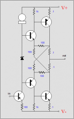
But, merely having opposite polarity transistors connected to opposite power supply rails does not make a cross-coupled buffer... perhaps in that few second look at the schematic I missed something crucial.
Doesn't make it a bad circuit though...
_-_-bear
But, merely having opposite polarity transistors connected to opposite power supply rails does not make a cross-coupled buffer... perhaps in that few second look at the schematic I missed something crucial.
Doesn't make it a bad circuit though...
_-_-bear
bear said:Forgive me in advance if I am incorrect?
But, merely having opposite polarity transistors connected to opposite power supply rails does not make a cross-coupled buffer... perhaps in that few second look at the schematic I missed something crucial.
Doesn't make it a bad circuit though...
_-_-bear
I have no idea what you are trying to get at. 🙂
It's a typical diamond buffer output stage.
Cheers!
Russ
Wherein the x-coupling involves feedback from the output stage back to the input stage via the "cross coupling"... the whole thing following its collective tail, that being a unity gain buffer. Perhaps this isn't the same thing as the "diamond buffer" idea. Or perhaps this sort of thing has been discredited measurement wise, or in terms of listening? Not to worry, I am easily distracted and confused! 😀
regards,
_-_-bear
regards,
_-_-bear
That's a complementary feedback pair... I know it well. 🙂
I have used it. Just not here.
Cheers!
Russ
I have used it. Just not here.
Cheers!
Russ
...what about without the two 100 ohm resistors that are between the two upper transistors and the bottom two transistors... the horizontal ones, and assume the outputs to be flipped, as is the stage before, emitter to the output... of course that is a differnt circuit, but it is the idea I'm aiming at...
_-_-bear
edit 3: I noticed a simplified version of what I use is mentioned in post 3 here: http://www.diyaudio.com/forums/showthread.php?s=&threadid=125378&perpage=35&pagenumber=1
_-_-bear
edit 3: I noticed a simplified version of what I use is mentioned in post 3 here: http://www.diyaudio.com/forums/showthread.php?s=&threadid=125378&perpage=35&pagenumber=1
I have now started to populate two of the boards. Of course, I now realize that I dont have a +-15V psu at hand 
I was hoping that the two swedish guys that showed interest in the boards would chime in, because someone needs to try these boards out before any groupbuy can take place.
I was hoping that the two swedish guys that showed interest in the boards would chime in, because someone needs to try these boards out before any groupbuy can take place.
- Home
- Amplifiers
- Solid State
- Diamante -a discrete medium power opamp