Hey guys,
I'm having some problems with my first build of a bass preamp mostly copying the Alembic F2B, with only 1 channel and an added cathode follower stage. Some of you on this forum helped me considerably when I was building it so thank you!
The tone stack is not working correctly. The mid control seems to work, but the bass and treble controls do nothing to the signal. Also, both the gain and volume controls distort considerably anywhere past 9oclock, to the point where the preamp is unusable. I had thought I would struggle to get enough gain from the one12ax7 tube and one stage of 12au7 for gain, but there is wayyyy more than I would think is normal.
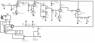
My thinking is that the tone stack just isn't making it into the circuit, so the attenuation I would expect from it isn't happening, explaining both the too-high gain and non-functioning bass and treble controls. I have triple checked my wiring and checked all grounds for continuity, checked my resistors, I just can't think of what else to do here besides ripping out the whole tone circuit and doing it again. Before I do anything like that, hopefully someone can chime in whether this circuit SHOULD work if it is wired correctly, and possibly any hints at where the problem could be, I can give any more information that is needed. Schematic attached.
Much appreciated, thanks. I know this is a sort of wild-goose chase over the internet but even sitting here looking at it I feel like I'm the one chasing the goose....
I'm having some problems with my first build of a bass preamp mostly copying the Alembic F2B, with only 1 channel and an added cathode follower stage. Some of you on this forum helped me considerably when I was building it so thank you!
The tone stack is not working correctly. The mid control seems to work, but the bass and treble controls do nothing to the signal. Also, both the gain and volume controls distort considerably anywhere past 9oclock, to the point where the preamp is unusable. I had thought I would struggle to get enough gain from the one12ax7 tube and one stage of 12au7 for gain, but there is wayyyy more than I would think is normal.
My thinking is that the tone stack just isn't making it into the circuit, so the attenuation I would expect from it isn't happening, explaining both the too-high gain and non-functioning bass and treble controls. I have triple checked my wiring and checked all grounds for continuity, checked my resistors, I just can't think of what else to do here besides ripping out the whole tone circuit and doing it again. Before I do anything like that, hopefully someone can chime in whether this circuit SHOULD work if it is wired correctly, and possibly any hints at where the problem could be, I can give any more information that is needed. Schematic attached.
Much appreciated, thanks. I know this is a sort of wild-goose chase over the internet but even sitting here looking at it I feel like I'm the one chasing the goose....
Attachments
 Moved to Instruments & Amps per forum policy
That is not the Alembic preamp by any means, you added 2 gain stages to an already sensitive design and turned it ito a Metal Guitar monster.
Build a straight F2B as per the original schematic, and instead of a cathode follower just use a 100k:22k or even 100k:10k attenuator at the output, which will give you both proper level and impedance to drive a typical SS amplifier.
Suggestion includes using original Fender type tone controls, not the Marshall inspired one you used.
Functional test: if properly wired, zeroing all 3 tone controls fully mutes output.
Opening tone pots one by one will give you treble, middle or Bass sound, which then you can mix at will.
That does not happen on Marshall type controls you show, so it´s harder to find they are working properly or not.
Seriousy, rip everything out and build the F2B , you won´t "repair" the current one which is flawed by design.
That is not the Alembic preamp by any means, you added 2 gain stages to an already sensitive design and turned it ito a Metal Guitar monster.
Build a straight F2B as per the original schematic, and instead of a cathode follower just use a 100k:22k or even 100k:10k attenuator at the output, which will give you both proper level and impedance to drive a typical SS amplifier.
Suggestion includes using original Fender type tone controls, not the Marshall inspired one you used.
Functional test: if properly wired, zeroing all 3 tone controls fully mutes output.
Opening tone pots one by one will give you treble, middle or Bass sound, which then you can mix at will.
That does not happen on Marshall type controls you show, so it´s harder to find they are working properly or not.
Seriousy, rip everything out and build the F2B , you won´t "repair" the current one which is flawed by design.
This circuit was pieced together from various opinions and websites, so if its a gross metal beast by design then I will most definitely just change it over to exactly an F2B. I thought that the cathode follower was going to be necessary to run SS power amps, and then wanted to make use of the other tride of 12au7 so just threw it into the mix 🙂. This has been mostly for my noob learning. So then to use the attentuator instead are you just saying like a passive circuit of resistors or like some external box?
Just two resistors, that's all....attentuator...like a passive circuit of resistors or like some external box?
Your triodes are fed from a 300-volt power supply, so the output from the 12AU7 can be up to 250 volts peak to peak. This will fry any solid-state amp to which it's connected.
The 100k:10k attenuator Fahey suggested will cut that down to maybe 25 V pp, worst case. It will also reduce output impedance to about 10k, which is good enough for a tube preamp, as long as you don't run a long length of cable from preamp to power amp.
IMO, 25 V pp is still dangerously large, but you have volume and gain pots, and as long as you use them sensibly, your power amp shouldn't be in too much danger. Or you can add overvoltage protection at your preamp output, such as a pair of reverse-parallel white LEDs, or reverse-series Zener diodes.
The white LEDs I've measured start to limit the signal at maybe four to five volts peak to peak, which should be sufficient for full output from most solid-state power amplifiers, and also low enough not to endanger them.
-Gnobuddy
Just two resistors, that's all.
Your triodes are fed from a 300-volt power supply, so the output from the 12AU7 can be up to 250 volts peak to peak. This will fry any solid-state amp to which it's connected.
The 100k:10k attenuator Fahey suggested will cut that down to maybe 25 V pp, worst case. It will also reduce output impedance to about 10k, which is good enough for a tube preamp, as long as you don't run a long length of cable from preamp to power amp.
IMO, 25 V pp is still dangerously large, but you have volume and gain pots, and as long as you use them sensibly, your power amp shouldn't be in too much danger. Or you can add overvoltage protection at your preamp output, such as a pair of reverse-parallel white LEDs, or reverse-series Zener diodes.
The white LEDs I've measured start to limit the signal at maybe four to five volts peak to peak, which should be sufficient for full output from most solid-state power amplifiers, and also low enough not to endanger them.
-Gnobuddy
Ok thanks for that clarification on the attenuator, so it's just a 100k resistor between plate and output with a parallel 10k resistor to ground if I'm doing my homework right?
Instead of trying to reinvent the wheel like I have been doing, I think I am going to convert this into a strict F2B clone, and then see if I need any attenuation or cathode follower if impedance mismatch seems to be a problem with my power amps (it seems a lot of F-2B users have reported few problems interfacing with solid state power amps, on paper the output impedance looks like a problem but in practice I haven't read too many actual concerns from users).
Thank you all for the input
Exactly, and it works just like a volume control set permanently to one position....so it's just a 100k resistor between plate and output with a parallel 10k resistor to ground...
A half-12AX7 with a 100k anode load will have an output impedance of roughly 40k. This is high enough to make proper audio engineers tut-tut and shake their heads sadly, and it would be unacceptable in a recording studio, but it's not high enough to cause a problem with most solid-state power amplifiers, particularly instrument amplifiers....on paper the output impedance looks like a problem but in practice I haven't read too many actual concerns from users.
The effect of too high an output impedance is subtle: it increases susceptibility to hum and noise pickup, and it may cause a slight loss of the highest treble frequencies if very long shielded cables are used between preamp and power amp.
If you keep the cables to a sensible length, hum shouldn't be a problem. And slight treble loss at 20 kHz is utterly unimportant for a bass guitar amplifier.
So I agree, there isn't really anything to worry about on the output impedance front.
But - it's a good idea to use an attenuator at the output. And this gives you two benefits, first it cuts down the signal, and second, it lowers the output impedance, if you choose sensible resistor values. The 100 k:10 k attenuator Fahey suggested will have an output impedance of around 10k, for example, four times lower than the half-12AX7 by itself.
-Gnobuddy
Exactly, and it works just like a volume control set permanently to one position.
A half-12AX7 with a 100k anode load will have an output impedance of roughly 40k. This is high enough to make proper audio engineers tut-tut and shake their heads sadly, and it would be unacceptable in a recording studio, but it's not high enough to cause a problem with most solid-state power amplifiers, particularly instrument amplifiers.
The effect of too high an output impedance is subtle: it increases susceptibility to hum and noise pickup, and it may cause a slight loss of the highest treble frequencies if very long shielded cables are used between preamp and power amp.
If you keep the cables to a sensible length, hum shouldn't be a problem. And slight treble loss at 20 kHz is utterly unimportant for a bass guitar amplifier.
So I agree, there isn't really anything to worry about on the output impedance front.
But - it's a good idea to use an attenuator at the output. And this gives you two benefits, first it cuts down the signal, and second, it lowers the output impedance, if you choose sensible resistor values. The 100 k:10 k attenuator Fahey suggested will have an output impedance of around 10k, for example, four times lower than the half-12AX7 by itself.
-Gnobuddy
This is great information, thank you.
So with this setup and output impedance being near 10k, should I think I can use this direct into recording consoles? Usually I use a Sansamp DI right after my bass, which gives a nice clear, albiet bland tone for recording that then I can tweak in the software, the rest of the signal chain/amp is only for the speaker in the room. It would be nice to think I could get some of that "tube-tone" into the recording interface when I want it. Probably something that I will just test myself once it's up and running...
Better question, is there any reason to use a potentiometer as the attenuator instead? More control? Or just kind of redundant?
Probably. This preamp doesn't have a balanced output, so there may be some trouble with hum. But I've used unbalanced equipment direct into a recording console without hum issues, so you may not experience any problem....I think I can use this direct into recording consoles?
In my opinion, a potentiometer by itself would be a bad choice: one twitch of your fingers, and your preamp can spit out 250 volts peak-to-peak, frying whatever solid-state gear it's plugged into.Better question, is there any reason to use a potentiometer as the attenuator instead?
You could use a 100k fixed resistor, and a 10k potentiometer to make up a variable attenuator that can't ever spit out more than 25 Vpp no matter where the pot is set; this would let you set the maximum output level when the preamp is at full drive. But: you already have gain and volume controls, do you need a front-panel output level control as well?
There is a third option, and probably the one I would use: a 100k fixed resistor, and a 10k (or 4.7k) trimpot. Overdrive the preamp, set the trimpot once and for all to your chosen maximum output level. Then leave it alone, and just use your existing gain and volume knobs.
-Gnobuddy
- Home
- Live Sound
- Instruments and Amps
- Diagnosing problems in first preamp