Hi everyone,
So I just had my old vibe slick a0 amp die on me. I hadn't realised but it had been running at bridged 1ohm this whole time so honestly surprised it lasted this long. It is rated for bridged 4ohm 200w.
One channel still works but hits protect when you turn it up too much, and the other hits protect as soon as a load is connected (even 4ohm). In bridged it hits protect immediately after being loaded by any speaker even idle.
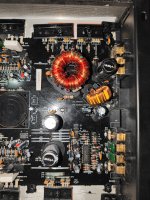
I've opened it up and the board looks ok, possibly some burn marks on the resistors, or not sure if that's just the black residue that looks like it was there from the factory (attached some pictures)
Anyway I'm thinking to replace the transistors anyway, they are currently k d998 and k b778 transistors. Does anyone know what I can swap them with as I can't find these anymore? I am in the UK. I can find 2sc5200 and it's complement (2sc1943?) for a pretty good price and readily available. Would these work?
If anyone has any other suggestions on what might need replacing or other alternative transistors to use any suggestions would be appreciated!
Thanks
Gershy13
So I just had my old vibe slick a0 amp die on me. I hadn't realised but it had been running at bridged 1ohm this whole time so honestly surprised it lasted this long. It is rated for bridged 4ohm 200w.
One channel still works but hits protect when you turn it up too much, and the other hits protect as soon as a load is connected (even 4ohm). In bridged it hits protect immediately after being loaded by any speaker even idle.
I've opened it up and the board looks ok, possibly some burn marks on the resistors, or not sure if that's just the black residue that looks like it was there from the factory (attached some pictures)
Anyway I'm thinking to replace the transistors anyway, they are currently k d998 and k b778 transistors. Does anyone know what I can swap them with as I can't find these anymore? I am in the UK. I can find 2sc5200 and it's complement (2sc1943?) for a pretty good price and readily available. Would these work?
If anyone has any other suggestions on what might need replacing or other alternative transistors to use any suggestions would be appreciated!
Thanks
Gershy13
Attachments
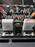
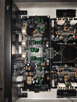
Before doing anything else, I'd suggest very carefully checking the value and the solder connections on the large 0.2 ohm 5 watt emitter resistors.
If you replace any parts, do not buy from eBay Amazon or the like. Buy semiconductors only from reputable parts distributors (Farnell... Others).
If you replace any parts, do not buy from eBay Amazon or the like. Buy semiconductors only from reputable parts distributors (Farnell... Others).

Solder connections look fine to my eye. I will try and measure the resistors. What should I be looking for as red flags on the multimeter? I plan to source my parts from RS components in the UK.
You're looking to see if they're within tolerance (±5% of the marked value of 0.2 ohms).
Do you have any experience measuring low value resistors?
Do you have any experience measuring low value resistors?
Unfortunately no experience with a multimeter other than basic voltage measurement and continuity testing. Slightly concerned that my multimeter or leads might not be suitable for the job, as touching them to each other shows values between 2ohms to 20ohms depending on the position of each tip on each other.
Hold the tips together tightly and rotate the plugs where they go into the meter. Does this change anything?
Nothing changes. As long as I hold them together tight the resistance is around 1.2ohms. I guess just a loose connection measures higher?
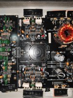
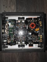
Trying to measure the resistors, attaching a pic of the back of the PCB. They seem fine on my multimeter. I am getting around 1.3-1.4ohms. which makes sense due to the leads resistance?

Nope it does not. So I have prodded around the board a bit. Interestingly those resistors are measuring 0.8ohms on my meter when pressed as tightly to the solder/pin on the back as I can.
What else should I be looking to measure and confirm where the issue lies? I can't seem to find anything that would show anything is dead or weak connections.
What else should I be looking to measure and confirm where the issue lies? I can't seem to find anything that would show anything is dead or weak connections.
Typically, in this type of amplifier, the over-current protection senses the voltage drop across those 5w resistors (emitter resistors). The attached diagram should be roughly similar. In that diagram, Q116 and Q216 are the sense transistors, pull and check them out of the circuit.
Attachments
You mean desolder them and test them in their own? The amp no longer goes into protect only under load. It is going into protect instantly on power on.
Is this without those transistors in the circuit?
Did you possibly allow any of the transistors to overheat by operating it out of the heatsink?
Did you possibly allow any of the transistors to overheat by operating it out of the heatsink?
The transistors are still in, I have not removed anything from the board yet. It was placed on the heatsink, although not strapped down. However the amp turned into protect basically immediately, I'd assume the transistors didn't even get time to warm up very much (unless they do extremely quickly)
I assume my next step for testing is removing some components from the board? Could you guide me on what I should remove first? The transistors or those ceramic resistors you mentioned.
I assume my next step for testing is removing some components from the board? Could you guide me on what I should remove first? The transistors or those ceramic resistors you mentioned.
Remove the two transistors (corresponding to Q116 and Q216). Does it still go into protect?
What are you using for a 12v supply?
What are you using for a 12v supply?
Sorry I am new to this and don't really understand how to read a circuit diagram, I found q116 and q216 in your pdf diagram, but i am not sure where it would be on my board? I assume it is one of these smaller D shaped transistors, not the big d998 style one? Would it be the one of the ones right next to the 5w ceramic resistor?
For power supplies, i am using one of those 400w switching LED style PSUs. It is 12v 33a. I have been using it for a few years now with this amp and sub and it was working fine. I think it is set to around 13.6v as that is what the amp manual said rms was tested at. (https://www.amazon.co.uk/Adapter-Aluminum-S-400-12(12V-400W)AC110-220V±15/dp/B08K4M7733) similar to that model, but not that exact one

For power supplies, i am using one of those 400w switching LED style PSUs. It is 12v 33a. I have been using it for a few years now with this amp and sub and it was working fine. I think it is set to around 13.6v as that is what the amp manual said rms was tested at. (https://www.amazon.co.uk/Adapter-Aluminum-S-400-12(12V-400W)AC110-220V±15/dp/B08K4M7733) similar to that model, but not that exact one
It doesn't have to be an exact diagram. Look for connections of a small TO-92 to the emitter resistor.
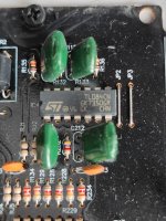
Apologies if i am being stupid, but I can't seem to figure out which one that would be on the board? I tried looking at the PCB traces to see what connects to the emitter resistor, but i can only see it being connected to the D998 style transistor? Would it be this small one that is hanging off the board?

Or the ones circled here?

Or the ones circled here?
- Home
- General Interest
- Car Audio
- Diagnosing and repairing Vibe Slick a0 amp?