The small donut shaped areas of copper on the board, where the components leg are soldered are "pads". The lines of copper connecting one pad to another are called traces... or tracks if you're British.
What the guys are talking about is this: If you can wiggle it and get it to work, the problem is probably NOT the transitor. It could be a tiny, real tiny, crack in the copper somewhere. Maybe between the pad and the trace. You may need a magnifier or loupe to see it.
Point is... you need to pinpoint your problem. Otherwise a new a part won't help you.
🙂
Hi poobah,
You are correct as always.
stonedfenix,
-Chris
You are correct as always.
stonedfenix,
No there isn't. It's not an opinion. You need to at least check the bias current. Period, end of story.Since there is some difference of opinion on whether the bias current will need to be adjusted, I'll try to make it easier.
-Chris
Hi guys,
How do you adjust the bias, I've tried searching around and my best guess would be adding resistors?
How do you adjust the bias, I've tried searching around and my best guess would be adding resistors?
Anatech, perhaps I do have somewhat too a high regard of modern product design...
The bias can be adjusted with a pot. It's a mono amp (for the subwoofer), so if the amp is not too complex, there is probably one potmeter somewhere in the poweramplifier section. That would be the bias control.
But, don't touch it yet. The pad stuff: let me make a drawing. This is a crosssection of a PCB:
It's possible you have the broken pad scenario. As you can see, resoldering the pad in quesation has no use. Fix it like illustrated, with the wire. You can't reattach the pad to the track.
The bias can be adjusted with a pot. It's a mono amp (for the subwoofer), so if the amp is not too complex, there is probably one potmeter somewhere in the poweramplifier section. That would be the bias control.
But, don't touch it yet. The pad stuff: let me make a drawing. This is a crosssection of a PCB:
An externally hosted image should be here but it was not working when we last tested it.
It's possible you have the broken pad scenario. As you can see, resoldering the pad in quesation has no use. Fix it like illustrated, with the wire. You can't reattach the pad to the track.
Hi halfgaar,
After being in service for years, I am cynical for good reason. 😉
I must say, beautiful illustration. You've shown that perfectly. Do you do textbook illustration by chance?
Hi stonedfenix,
Did you mention the make and model? I can't remember if you did. Without the unit on my bench in front of me, I can't offer any safe advice.
-Chris
Hi guys,
thank you halfgaar for that easy to understand drawing. I couldn't see any cracks in the track though. The strange thing though is that there is only one track leading from the 3 pads. the other 2 dont seem to have any. I check both sides of the pcb. I guess I'll have to dig out my multimeter to check for sure. But in any case, in my haste and curiosity I have destroyed the transistor in my attempt to open it. It seemed much more easier than it was, so I guess I have to order the part now.
Thanks everyone for your input, it is much appreciated. But one more noob question.
How do I check the bias?
I know of this much so far from the datasheet,
the pins on the trans are labeled "B C E" so I suppose I test one pin with one lead of the multimeter and one of the others with the other lead. But which ones?
What voltage or current am I aiming for? There are numbers for Vcbo, Vceo,Vce,Ic,Tj and so forth.
How can I adjust the trans? Do I solder it in place then test it while adjusting the pot and do I plug in the power cord and turn it on.
I know this is asking alot but if this is too much to explain, can you direct me to a link that is noob friendly.
Again, I thank everyone for your helpful input.
I must say, beautiful illustration. You've shown that perfectly. Do you do textbook illustration by chance?
No. I do however, make drawings like this for forums more often 🙂
I couldn't see any cracks in the track though.
You can't often. That's where the multimeter comes in handy. Especially one with audible continuity test. Connect it to two pads of one track and wiggle the transistor. If it interrupts, you'll have a suspect.
The strange thing though is that there is only one track leading from the 3 pads. the other 2 dont seem to have any. I check both sides of the pcb.
It's possible that it's a multilayer PCB. In that case, you could have somewhat more difficulty. If an internal layer has come of the "via" (the metal bushes in the holes), you need to figure out where it was supposed to connect to. If it makes intermittent contact, you may be in luck of finding the orignal connection. Otherwise, you may need to reserve engineer the schematic...
And, desoldering components from via's is tricky. Via's are easiy damaged. I suggest using desoldering braid, to empty both sides of the via. I just recapped another computer mainboard, and found out that even for vias, desoldering braid works much better than a solder sucker. The latter can be quite destructive...
But in any case, in my haste and curiosity I have destroyed the transistor in my attempt to open it. It seemed much more easier than it was, so I guess I have to order the part now.
I remember me saying something about opening a transistor and expecting it to still work (meaning, that you can't)....
How do I check the bias?
A post I made a earlier describes it in detail.
the pins on the trans are labeled "B C E" so I suppose I test one pin with one lead of the multimeter and one of the others with the other lead. But which ones?
Either the collectors or emitters of both transistors connect to eachother through two low value power resistors. It's the collectors, put the probes on both collectors, if it's the emitters, put them on the emittors. And, don't accidently short anything !
What voltage or current am I aiming for?
(...)
How can I adjust the trans? Do I solder it in place then test it while adjusting the pot and do I plug in the power cord and turn it on.
It would have been best if you had measured the original value first, before making modifications. You have now lost that ability, because the transistor is bust. I don't know if there is a standard voltage you can use. Perhaps others do?
You adjust it while the device is powered. Measure the voltage over the output resistors constantly, and change the pot until the desired voltage is reached. This is dependant on temperature. If there is a standard voltage you can use, you must know first if that's the cold or warm value. In case of the latter, let it stabilize temperature wise after each adjustment.
Hi stonedfenix,
The very first thing you should have done was obtained the service information for your unit. I know all kinds of shortcuts and ways to figure things out, but not if the unit is not on the bench in front of me.
I will recommend you put the unit aside until you get the information. You can email it to members who are trying to help you, thaty way we can properly advise you.
-Chris
What is the service information? the circit diagram? I've looked and googled every combination I can think of can find anything on it. The model is AT2100i from KLH in case you need it.
Yes I realized my stupidity in destroying my only clue.
Whats the worst that can happen with an misadjusted transistor. Cant I turn it to the lowest setting(or highest, be it clockwise or counter) first and adjust it from there.
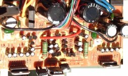
In any case I couldn't find any thing that resembles a pot, which I imagine to be a wheel like or flat head screw knob thing. I attached a pic but I have no macro lens so this is the best I got.
Yes I realized my stupidity in destroying my only clue.
Whats the worst that can happen with an misadjusted transistor. Cant I turn it to the lowest setting(or highest, be it clockwise or counter) first and adjust it from there.
In any case I couldn't find any thing that resembles a pot, which I imagine to be a wheel like or flat head screw knob thing. I attached a pic but I have no macro lens so this is the best I got.
Attachments
Hi stonedfenix, From your picture of the amp, it looks like that transistor has nothing to do with the power amp itself. It looks like those multi-legged things with the metal tab are your power amp IC's.
....I'm adding this link. <http://www.klhaudio.com/warranty.htm> You could ask KLH for a manual. I don't know they'll sell, or not. I didn't get the sense that theywere a well funded part of KLH program.
....I'm adding this link. <http://www.klhaudio.com/warranty.htm> You could ask KLH for a manual. I don't know they'll sell, or not. I didn't get the sense that theywere a well funded part of KLH program.
Hi stonedfenix,
I second mrshow4u's recommendations.
Those IC's look like the amplifier chips. The transistors may switch in a higher voltage supply when needed as a total guess.
-Chris
I second mrshow4u's recommendations.
Those IC's look like the amplifier chips. The transistors may switch in a higher voltage supply when needed as a total guess.
-Chris
I would think those power opamps are for the satelites, and that the two transistors in the middle are for the subwoofer. This was the arrangement in a home cinema satelite set I had to repair a while back. The only thing I can't figure is why there would be two, because I thought it was a 2.1 system (it is 2.1, and not 4.1, right?).
But there indeed doesn't seem to be anything like a pot. Perhaps they didn't wanna go through the trouble of proper calibration, and just used a value that mostly works.
Should biasing have been possible, the worst that can happen with wrong calibration, is thermal runaway. After that, distortion. If you can't obtain a service manual, I'd just slap in a new transistor and see if it works. I mean, if there is no bias control, there is not much you can do.
As for turning it all the way up or down; if you know what to calibrate for, turning it all the way down first is a safe bet. But, you probably won't know what up or down is, and if you accidently put it at maximum, you can instanty destroy something. Therefore, the best option is to leave it as it is, and adjust carefully to obtain the proper setting.
Another thing. When putting it back together, make sure every transistor makes contact with the heatsink as it did before you took it off. This can be important for thermal stability.
That is a good call halfgaar. I got the feeling this sub's x-over/amp were fed with speaker wire. (...and maybe they still are). So maybe this thing is fed with line level signals? I thinks it's time stonedfenix MUST get a service manual.I would think those power opamps are for the satelites, and that the two transistors in the middle are for the subwoofer.
Sorry stoned, I think it's time to admit that better information is needed to move in the right direction. A wrong turn in this area of troubleshooting could cause fire, electrocution, or both. Bad things still happen to seasoned pro's too. It's just that they mostly are going to know what could go wrong. They tend to know where to look for mechanical problems (solder cracks, etc) and when and how to adjust bias. There a lot of things to monitor. Thermal, distortion, oscillation. These are just a few things to be mindful of when repairing/designing equipment. To be good at electronics, takes a long time. You will never know it all. No one will. It's fun all (most) of the way. There is no end. I really recommend the service manual. It will be a great way to really apply reading a schematic to fixing a problem. That's the best way to learn.
About the bias on these things. If the sub amp's output stage is the two TO-3P package transistors, maybe there is no bias pot? Maybe they just run it dirty (under-biased). There is what might be a thermistor in the photo. The power amp IC's (satellites) might have their own internal biasing scheme.
I definitely don't want one of these KLH's after seeing the inside. Hey stonedfenix, maybe this would be a good time to start on a subwoofer project??
....I looked at the picture again. That yellow adhesive on the top side of the PCB. I've seen stuff that looks like that get conductive over the years and cause these "noisey amp" fault. That would be another thing to check, if the noise hasn't gone away through part eplacement or other.
The Project68 subwoofer amp by Rod Elliott also doesn't have a bias control. It is biased by two diodes, which are in thermal contact with the driver heatsink. Rod admits that for normal use, the distortion is too high, but for subwoofer operation, it doesn't matter. The amp in the HKL is used as sub only, so perhaps they used the same reasoning.
BTW, the order for my replacement transistors is just in, so I hope to find out soon if replacing the differential stage in the Erres amp is going to work.
BTW, the order for my replacement transistors is just in, so I hope to find out soon if replacing the differential stage in the Erres amp is going to work.
I hope you nail it.BTW, the order for my replacement transistors is just in, so I hope to find out soon if replacing the differential stage in the Erres amp is going to work.
A separate channel for subwoofer duty makes good sense if this runs a pair of satellites. I hope they had it underbiased slightly. The woofer mass then acts as a filter to reduce the sound of crossover distortion.
Hi halfgaar,
Let us know how you do with your subs. You need to match the diff pair.
-Chris
Hi halfgaar,
Let us know how you do with your subs. You need to match the diff pair.
-Chris
Thank you everybody for your help and insight. I will try to obtain a service manual before I move foward with my repairs. In the mean while I will read up on simple electronics. Thanks guys.
Let us know how you do with your subs. You need to match the diff pair.
Hmm, I never matched transistors for the diff pair. I ordered three, because that was the minimum order amount, so I don't have many spare ones to create matched a diff pair... But, I will use the ones which are most equal.
In the mean while I will read up on simple electronics. Thanks guys.
When you've got the basics down, get into audio electronics. General electronic knowledge won't supply you with enough information. I recommend Rod Elliott's website.
BTW, I think, that the HKL amp will work within factory parameters if you just replace the transistor (if it was the transistor at all, that is). They obviously didn't care about varying transistor specs (judging by the lack of bias control). I still agree with what mrshow4u said, but I also think that this particular amp could work nicely (as in, the limits accepted by the manufacturer) with a simple transistor swap. Just mount it and the heatsink as it was before (and check the heatsink doesn't come in electrical contact with one of the transistors). Pay attention to the heatsink that it doesn't get warm fast (that would mean oscillation most likely). Play a loud sine tone to warm up the heatsink (not too loud and not too long), stop the tone and determine if the heatsink cools down again (if not, you've got thermal runaway). If it also sounds OK, then everything is probably fine.
- Home
- Amplifiers
- Solid State
- Diagnosing and fixing amplifier fault (loud crackling and popping)