You're correct about the scale. I had my probes at 0.1X and hadn't realized. This scope is new to me and I'm not used to its features yet. Input signal was indeed ~400mVpp in all measurements above. (I double checked with a cheap old scope that I know better.)
Trying again with an actual 40mVpp signal, the latest results still look similar at the scale I thought I was looking at.
Trying again with an actual 40mVpp signal, the latest results still look similar at the scale I thought I was looking at.
Last edited:
Just to establish some clarity after so many changes, I redid DC voltage measurements now that the bad connection is fixed. No surprises there, everything looks about the same.
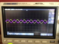
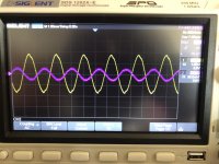
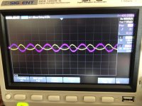
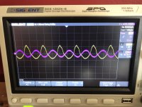
Here are some results measuring input and output with 1X probes and a signal more in the range I would normally use:
No load, volume low-ish:

No load, volume max:

8R dummy load, volume low-ish:

8R dummy load, volume max:

Hopefully this gives us a clear picture to proceed from. Not sure whether the other measurements recommended make sense now that the no-load situation looks so much better.
Here are some results measuring input and output with 1X probes and a signal more in the range I would normally use:
No load, volume low-ish:

No load, volume max:

8R dummy load, volume low-ish:

8R dummy load, volume max:

Hopefully this gives us a clear picture to proceed from. Not sure whether the other measurements recommended make sense now that the no-load situation looks so much better.
Clear enough.
Solving the poor connection other intermediate measurements are not needed any more, they would have pinpointed *where* was signal lost.
Difference between proper troubleshooting and shotgunning (which I hate) which depends on chance.
And as you see, problem was not caused by a "bad part", you could have tested all outside or even replaced all with fresh ones and STILL not solved the problem, many times problems come from bad connections, wiring errors, poor adjustment or even operator error.
Back to the problem: I suspect your amplifier, **as built**, simply can not drive 8 ohm, period.
That "no drivers" design was popular once, when transistors were *expensive* and saving on 2 meant something, not today.
Your TIP29/30 Hfe, current gain, must be lower than that of original ones (which probably were specially selected) , rated current gain can vary between 15 (ludicrous) and 75 (good) at 1A and to boot they are 1A MAX ; very marginal.
So this circuit *can* work (it did for Gibson) but it´s "too close to the edge" and needs specially selected parts.
Personally, and to save your Project, on which you already invested time and money, I´d play it very safe and improve output transistors, that will NOT change sound.
To avoid increasing parts count, I´d add drivers by replacing original TIP by Darlingtons (which have them built-in).
You can replace TIP 29 by TIP120 -121 or 122 and TIP30 by TIP125 - 126 or 127, whichever you can get.
You will need to increase bias, easy by adding 1 or 2 extra diodes but leave that for later, now we are trying to fully drive that 8 ohm speaker.
OR you might replace TIP29/30 with TIP31/32 which have more "muscle" (3A MAX) and will have somewhat higher Hfe at 1A but you might be unlucky and again get low Hfe transistors.
None of that with Darlingtons, of course, which splurge with Hfe.
You will also need to change R15 to 1k or 2k2 since we do not need that much drive current any more.
Ok, flip a coin and choose 1 option 🙂
Last edited:
You could try D44H8 and D45H8. They have higher gain than the TIPs, handle more current, and have lower saturation voltage. Also in TO-220 and cheap. Use the H8 versions, the higher voltage H11 versions tend to have a little lower gain.
Hey!!! Nice find!!! 🙂
These will DEFINITELY work better than originals, and at guaranteed minimum Hfe=60 must properly drive an 8 ohm load with no further modifications.
Thanks.
These will DEFINITELY work better than originals, and at guaranteed minimum Hfe=60 must properly drive an 8 ohm load with no further modifications.
Thanks.
I decided to test the theory that the amp can't drive 8 ohms by using a 16 ohm speaker I had handy. Sure enough, it sounds clean! I think I can probably find some transistors around here with higher hfe / current capability...
I'm not sure I understand the role of R15. It's the path to ground for the Q3 collector, but being connected to positive feedback, I guess it's also a bootstrap, to increase the gain of Q3?
Thanks so much for your help, JMFahey. I'll post a video when I get it finished.
I'm not sure I understand the role of R15. It's the path to ground for the Q3 collector, but being connected to positive feedback, I guess it's also a bootstrap, to increase the gain of Q3?
Thanks so much for your help, JMFahey. I'll post a video when I get it finished.
You didn´t tell anybody where you live 😉
Please fill up that data in your profile, it´s very important to suggest answers, which vary a lot depending on where you are.
A dead 10" "factory speaker" in a guitar amp will be junked and replaced in USA and reconed in , say, South Africa, Argentina or, maybe, Poland.
A dead transformer will be straight replaced in USA and probably rewound in Poland (they have excellent winders which charge very reasonable prices) and so on.
$2 in Mouser parts may cost $60 in Argentina after expensive freight and heavy taxing.
> I'm not sure I understand the role of R15. It's the path to ground for the Q3 collector, but being connected to positive feedback, I guess it's also a bootstrap, to increase the gain of Q3?
You understand the role of R15.
You understand the role of R15.
> theory that the amp can't drive 8 ohms
To a very rough approximation, the amp can drive R15/hFE before it runs out of drive. Say 270/50, minimum 5.4 Ohms. Say 270/27 (lazy math), 10 Ohms. 270/15 is 18 Ohm minimum load.
For static DC load, this is really the half-voltage point. With capacitive boostrap AC load it gets complicated, but speech/music can work "OK" with the R15/hFE guesstimate.
R18 is not essential, but convenient when testing without a loudspeaker.
A 8-Ohm Ten really should have more than 500uFd coupling cap; another cheap-out.
I have not used 1,000uFd main cap since about the time this was sold; but that may be part of the "charm" (overload breakover and buzz).
Excellent explanation.
Digging a little deeper:
Which in this case is 15V(midpoint voltage)/R15=15V/270r=55.55mA
Forget R18 because in a working amp it´s bypassed by speaker DCR, some 7 ohm, which make it all but disappear.
So: unless you have a lot of Hfe (current gain) you will not have enough current to drive the speaker, it´s not more complicated by that.
To drive 8 ohm you need a MINIMUM GUARANTEED Hfe of 270/8=33.75
Gibson probably ordered batches of 10.000 selected/pretested transistors and manufacturers complied; we humble diyers get what´s available at the nearest shop.
The transistors PRR suggested earlier have guaranteed minimum Hfe of 50 or 70, so they are safe to buy and use untested.
If you have a lot of TIP29/30 you can select best BUT you must test them at 1A (not an easy thing) ; multimeters test them at, say, 1 or 2 mA: useless test.
If you can´t order the modern ones, try using TIP31/32 or even TIP41/42, being respectively 3A and 6A transistors (still in TO220 case), they will have "better" Hfe at 1A
Digging a little deeper:
R 15 sets the current available to drive Q4 and Q5 😱> I'm not sure I understand the role of R15. It's the path to ground for the Q3 collector, but being connected to positive feedback, I guess it's also a bootstrap, to increase the gain of Q3?
Which in this case is 15V(midpoint voltage)/R15=15V/270r=55.55mA
Forget R18 because in a working amp it´s bypassed by speaker DCR, some 7 ohm, which make it all but disappear.
So: unless you have a lot of Hfe (current gain) you will not have enough current to drive the speaker, it´s not more complicated by that.
Which PRR shows as:> theory that the amp can't drive 8 ohms
So if you got TIP29/30 with minimum Hfe = 15 (which is possible and shown in the datasheet) your amp can barely drive 18 ohm!!! 😱To a very rough approximation, the amp can drive R15/hFE before it runs out of drive. Say 270/50, minimum 5.4 Ohms. Say 270/27 (lazy math), 10 Ohms. 270/15 is 18 Ohm minimum load.
To drive 8 ohm you need a MINIMUM GUARANTEED Hfe of 270/8=33.75
Gibson probably ordered batches of 10.000 selected/pretested transistors and manufacturers complied; we humble diyers get what´s available at the nearest shop.
The transistors PRR suggested earlier have guaranteed minimum Hfe of 50 or 70, so they are safe to buy and use untested.
If you have a lot of TIP29/30 you can select best BUT you must test them at 1A (not an easy thing) ; multimeters test them at, say, 1 or 2 mA: useless test.
If you can´t order the modern ones, try using TIP31/32 or even TIP41/42, being respectively 3A and 6A transistors (still in TO220 case), they will have "better" Hfe at 1A
Last edited:
I'm in the USA (California), so ordering parts from Mouser is easy here. That said, I think I have some spare TIP41/42 on hand already from when I was first learning about push-pull output stages. If those work well I probably won't bother with ordering Darlingtons / D4XH8.
Still searching for an appropriate speaker...
Still searching for an appropriate speaker...
It doesn't increase the gain, but it increases the voltage range for Q5's base. As the output goes negative, it pulls the right side if R15 well below zero volts, providing more current to Q5's base so that it can operate down to near zero volts on its emitter. If the right side of R15 went to ground it wouldn't provide as much current to Q5's base when the base voltage went near zero volts, and the base voltage wouldn't go as low. I've seen similar bootstrapping with a separate capacitor, but this one "conveniently" uses the output capacitor.I decided to test the theory that the amp can't drive 8 ohms by using a 16 ohm speaker I had handy. Sure enough, it sounds clean! I think I can probably find some transistors around here with higher hfe / current capability...
I'm not sure I understand the role of R15. It's the path to ground for the Q3 collector, but being connected to positive feedback, I guess it's also a bootstrap, to increase the gain of Q3?
After switching over to TIP41/42, I appear to have had good luck on their hfe and the amp sounds much better driving my 8 ohm test speaker.
One thing I did notice (both before and after swapping the output transistors) is that the 2n4402 (Q3) is running quite hot. If I'm doing my math right, it's dissipating ~800mW, well above its 625mW spec. Maybe the result of more razor's-edge cost saving by Gibson? I was thinking I might put a spare TIP30 in there instead — looking at the data sheet, I don't see any reason I understand why that wouldn't work. Is it a bad idea for a reason I don't understand?
One thing I did notice (both before and after swapping the output transistors) is that the 2n4402 (Q3) is running quite hot. If I'm doing my math right, it's dissipating ~800mW, well above its 625mW spec. Maybe the result of more razor's-edge cost saving by Gibson? I was thinking I might put a spare TIP30 in there instead — looking at the data sheet, I don't see any reason I understand why that wouldn't work. Is it a bad idea for a reason I don't understand?
....Which PRR shows as:
The transistors PRR suggested .....
I did not suggest a part.
I did wrongly write "270" several times when the drawing shows 220.
Doing R and hFE is the-same-as doing V and I.
As for Q3 heat: looks like 11V in 220 ohms or 0.55 Watts. Which "IS" legal. But sure will run hot. But hasn't it apparently run hot for 47 years? If it was gonna burn-up it should be ash now; if not, it probably has many years/cycles left.
Isn't the 2N4402 a higher FT part than TIP30? Yup, nominally 50X faster. (I'm not sure the 1970 numbers are true on modern process, but the smaller die is liable to be faster.) Despite simplicity this is a high NFB design and is liable to squeal MHz unless gain-slope is controlled.
Quote:
Originally Posted by JMFahey View Post
....Which PRR shows as:
The transistors PRR suggested .....
I did not suggest a part.
Ooops, you are right, it was WG-SKY, so kudos to him instead 🙂
You could try D44H8 and D45H8. They have higher gain than the TIPs, handle more current, and have lower saturation voltage. Also in TO-220 and cheap. Use the H8 versions, the higher voltage H11 versions tend to have a little lower gain.
My mistake for trusting my feeble memory.
PRR, how do you figure 11V in 220R == Q3 Pd? Maybe I'm doing something wrong. My calculation went like this:
Q3 E at 28.6V - Q3 C at 13.2V = 15.4 Vce. For current I also looked at R15 for a good approximation, where I see 12.3V on one side and ~0.5V on the other side, so 11.8V / 220R = 54mA. Then I figured >54mA dropping 15.4V is >0.8W.
Q3 E at 28.6V - Q3 C at 13.2V = 15.4 Vce. For current I also looked at R15 for a good approximation, where I see 12.3V on one side and ~0.5V on the other side, so 11.8V / 220R = 54mA. Then I figured >54mA dropping 15.4V is >0.8W.
> how do you figure
I may be misreading the schematic.
575200B00000G Aavid | Mouser
575200B00000G | Heatsink, 60degC/W, Plug-On Collar | RS Components
TO-92 heat sink instant making at home - The RadioBoard Forums
I may be misreading the schematic.
575200B00000G Aavid | Mouser
575200B00000G | Heatsink, 60degC/W, Plug-On Collar | RS Components
TO-92 heat sink instant making at home - The RadioBoard Forums
For the price of a TO-92 heat sink you can get a “driver” or “VAS” transistor such as KSA1220 or KSA1381 to use in place of the 4402. Then you can use just any piece of scrap metal as a heat sink if you still think it runs too hot. A TIP30 probably won’t sound very good - I doubt it would actually oscillate.
There used to be a lot more choices for a fast-ish higher gain Transistor in a TO -126, To-39, or giant TO-92 case, but the push toward SMD has pushed almost all of them to obsolescence and unobtainium. If you find something like that in a piece of scrapped equipment you can give that a try. If you’re cheap and don’t want to put together an order just to get a $1 part that’s where I’d start.
There used to be a lot more choices for a fast-ish higher gain Transistor in a TO -126, To-39, or giant TO-92 case, but the push toward SMD has pushed almost all of them to obsolescence and unobtainium. If you find something like that in a piece of scrapped equipment you can give that a try. If you’re cheap and don’t want to put together an order just to get a $1 part that’s where I’d start.
Whatever the numbers: it does appear this was commercially sold (with some warranty?); and here it is 47 years later and Q3 is _not_ the one that fried. I don't think replacement/"upgrade" is urgent.
Though TO92 sinks "can" be made of "any" scrap metal. Find your drill bit a hair smaller than a TO-92. Bend beer-can metal around it, and hammer tight 359 degrees. Spread the legs.
Though TO92 sinks "can" be made of "any" scrap metal. Find your drill bit a hair smaller than a TO-92. Bend beer-can metal around it, and hammer tight 359 degrees. Spread the legs.
Well, speaking of the possibility of oscillation...
I got my hands on some TO-92 heatsinks, and found a good price on an old Jensen 6x9 (which I was curious to hear anyway — it's looking like MOD 10-35 may be the most affordable option for a 10" speaker if I don't like this one).
So, due to physical constraints the easiest thing was to clip the old 2n4402 out and install a new one with a heatsink, which I did... and then promptly found that it oscillates with the new 2n4402. With an 8 ohm load, it squeals at ~500kHz. With no load, no such problem. With a 16 ohm load, also no problem.
To aid investigation, I got set up to easily slot in different transistors for Q3. I don't understand what happened — all my 2n4402s seem to make it oscillate now. Just to see, I tried a TIP30, and it worked with no oscillation, and sounded good through my new speaker. A TIP42A also works fine and sounds good. A 2n3906 in this position induces oscillation.
I've double and triple checked that I'm installing the transistors the right way around, and that all connections seem good. I'm pretty much at a loss. What could possibly be going on here?
- Home
- Live Sound
- Instruments and Amps
- Diagnosing a simple transistor guitar amp