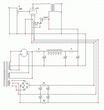
I am working on building an ultrapath headphone amp using a single DHT per side. The basic ultrapath schematic is very very simple, but I am having trouble converting it from IDHT to DHT. Attached is how I think it should be, but could use some help figuring out of thi is correct or not.
Essentially, the circuit is the same as the original, but the DHT filament is powered by +/-1.25V from a center tapped winding. The center tap then connects to the ultrapath cap then connects to ground through a resistor in order to bias the cathode. Is this the proper way to do this?
Essentially, the circuit is the same as the original, but the DHT filament is powered by +/-1.25V from a center tapped winding. The center tap then connects to the ultrapath cap then connects to ground through a resistor in order to bias the cathode. Is this the proper way to do this?
Attachments
To be frank I am not entirely sure, I can't see how running your audio path through the bridge is going to help matters.
FWIW, I would just take the signal out of one side of the heater and be done with it.
Failing that, put a pair of resistors across the heater that have a high enough resistance so as not to load down the heater supply, and pull a 'centre tap' from that.
hope that this helps.
kind regards
FWIW, I would just take the signal out of one side of the heater and be done with it.
Failing that, put a pair of resistors across the heater that have a high enough resistance so as not to load down the heater supply, and pull a 'centre tap' from that.
hope that this helps.
kind regards
I guess I see why running everything through a bridge is maybe not the best idea, but I am afraid that I don't understand the rest of what you are saying. Could you explain a little more?
Somehow I need to run 2.5V of very very clean DC through the filament, bias the filament up via a resistor, and attach a cap from between the resistor and the tube to B+. This seems like it should be so easy, and yet the solution just totally escapes me.
Somehow I need to run 2.5V of very very clean DC through the filament, bias the filament up via a resistor, and attach a cap from between the resistor and the tube to B+. This seems like it should be so easy, and yet the solution just totally escapes me.
Can you be more specific here? It sounds like a stupid question, but I just don't know what you mean.FWIW, I would just take the signal out of one side of the heater and be done with it.
Failing that, put a pair of resistors across the heater that have a high enough resistance so as not to load down the heater supply, and pull a 'centre tap' from that.
Hi
your new diagram is spot on.
Imagine now that you Iak is now flowing down [or up depending on how you look at it] through the two resistors, and then through the bias resistor.
If you keep the two resistors that define your mid point reasonably small [as a proportion of the bias resistor] there will be little change.
Say you make them 10 ohms each, this puts an extra 5 ohms, [they are effectively in parallel] into the bias resistor, nothing really.
They are also directly in parallel to the heater supply, so they add up to 20 ohms, now, your heater voltage is 2.5v if I remember correctly, therefore, the heater supply has to provide an addition 2.5/20 = 125mA,
this may be too much for you, so double the resistors, this gives an extra 10 ohms to bias, and now an extra 62.5ma in heater current.
Take it all the way up, and make them say, 50ohms, you have 25ohms extra in the bias, again, a bit triviail, but if you are worried about it, you can reduce the size of the bias resitor by 25 ohms, extra heater current is now 20ma, again trivial.
does this help?
kind regards
bill
billr said:does this help?
Tremendously. Thanks so much.
One other question, though. The ultrapath cap connects from the top of the cathode bias resistor. Does this suggest keeping those 2 resistors as small as possible to preserve the basic layout, or is that not so important.
- Status
- Not open for further replies.
- Home
- Amplifiers
- Tubes / Valves
- DHT Ultrapath Linestage schematic help

![ultrapath45[2].gif](/community/data/attachments/57/57617-862fcef31eec886098b14c5fe6737a66.jpg?hash=hi_O8x7siG)