kevinkr said:...so please take this as merely anecdotal.
No, I figured valid reasons backed your opinion and was curious. Mine is different though, I can check when back home but recall finding 40 uF ASC caps went self-resonant closer to 120 kHz, 100 uF around 75 kHz. Modern electrolytics probably do better because of the much smaller size but unless you're as ....persnickety as I am, and place caps directly at the load, wire harnesses will probably be the big equalizer.
Do you recall he E-Bay vendor? I wonder is 'AASC' or 'ASCC' caps are floating around.
mahleriana said:I don't know back-bias. I would be interested by the schematics.
Thanks in advance 45
eric
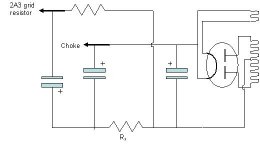
This is it!
As you can see the center tap of the transformer and the first cap are not grounded. They see the ground through the Rx resistance.
So, the total current of the amp will cause a drop at Rx which will be your bias!
Then you should add an additional RC filter in order to have a clean bias, before connecting to the grid resistor.
Rx could be a fixed resistor + a pot. The total value depends on the total current.
Considering 60 mAx2 and 3 mAx2 (for the 6922), you have 126 mA. Then you need 357 Ohm for 45V.
I would suggest to use a 50 Ohm/2W wirewound potentiometer plus 330 Ohm/10W resistor.
Cheers,
45
Attachments

About the 6992 you could go for: 560-680R cathote resistor, 18-22K anode resistor.
Using 240-250V, the anode current should be around 5 mA depending on the final values and the real tubes themselves!!
Using the 6922, you could reduce to 100-120K the 2A3 grid resistance together with a 1 uF cap.
IMHO, the SCR MPK 630Vdc caps are excellent.
Cheers,
45
Using 240-250V, the anode current should be around 5 mA depending on the final values and the real tubes themselves!!
Using the 6922, you could reduce to 100-120K the 2A3 grid resistance together with a 1 uF cap.
IMHO, the SCR MPK 630Vdc caps are excellent.
Cheers,
45
Here's a Loftin White topology, that is true to the original concept. This schematic is a take off on Darius's 300B design. You could use your 300-300 transformer with a bridge or hybrid bridge, and a 6SN7 for the driver and follower. It would drive your 2A3 fine.
Sheldon
Sheldon
Attachments
Several people have commented that the 6SL7 is not suitable. They are right. If I were you, and was worried about exotic tubes and the like, I would use a 6SN7 instead, and run a few mils on it. I would use about 27K or thereabouts for your plate load. You will get less gain but the driver will be a lot more effective. Try that (you will have to sort out the right cathode resistor value, and if it were me I would avoid bypassing it). If that seems like the right direction, then the next step will be obvious: for example whether to use the exotic DHT signal tubes.
IME you won't need a lot of gain because your speaker has to have high efficiency, or else you are wasting your time trying to use a 2A3. So you will be trading off gain for speed.
IME you won't need a lot of gain because your speaker has to have high efficiency, or else you are wasting your time trying to use a 2A3. So you will be trading off gain for speed.
...I had before that a class d amp (trends audio ta10.1) and the only thing i miss the former amp is its speed and transients. I find the tube amp slightly offbeat.
Honestly that's the only positive impression that always strikes me when listening to sand-amps; my guess is that the damping factor plays it's role there. The limited bandwith of your opts probably also has a part in the percepted slowness.
Simon
I'm not surprised you're having speed problems with that design. No way can a 6SL7 drive a 2A3, or any other audio final. The 6SL7 was designed to be a high gain, small signal amp. As such, it has eeeeeeeeeeeenormous static and dynamic plate resistance. There simply isn't enough current sourcing to charge up the 2A3's Cgk + Cmiller + Cstray fast enough. Until those capacitances charge up, the grid won't see the true signal level. And let's not forget that these DHTs have a bad habit of starting to pull grid current even before Vgk actually goes positive. When the grid is driven positive by a fast moving transient, that 6SL7 simply rolls over and dies.
That needs a cathode or source follower to drive the grid. A follower also presents the 6SL7 with the type of load it likes to see: Hi-Z and Lo-C. I would also ditch the cathode bias for the 2A3. Fixed bias is so much better for audio finals. The THD is frequently lower, and it has better clip behaviour when a fast transient comes along.
I see a lot of complaints like this one involving DHTs, and in every case, it's inadequate grid drive that's causing the problem.
45 said:
This is it!
As you can see the center tap of the transformer and the first cap are not grounded. They see the ground through the Rx resistance.
So, the total current of the amp will cause a drop at Rx which will be your bias!
Then you should add an additional RC filter in order to have a clean bias, before connecting to the grid resistor.
Rx could be a fixed resistor + a pot. The total value depends on the total current.
Considering 60 mAx2 and 3 mAx2 (for the 6922), you have 126 mA. Then you need 357 Ohm for 45V.
I would suggest to use a 50 Ohm/2W wirewound potentiometer plus 330 Ohm/10W resistor.
Cheers,
45
45,
Could you post the rest of the schematic, Brooks perhaps? I am interested in the rest of the circuit as well.
TIA,
korneluk said:
45,
Could you post the rest of the schematic, Brooks perhaps? I am interested in the rest of the circuit as well.
TIA,
Hi Korneluk, I don't have the schematic of the Brook amplifier right now.
If I am not wrong it should be the Brook 22a model. It is a 2A3 push-pull.
Cheers,
45
atmasphere said:Several people have commented that the 6SL7 is not suitable. They are right.
I imagined to use 6sl7 from jelabs design because Fi X amplifier also seemed to use this kind of tube :
Direct coupled using 1 single triode by channel for input/drive
this triode is 6sf5 : 66k Rp and 0.9 mA typical operating point and mu=100 : should be even worse than 6sl7 but this is used by a "renowned" designer...with rave reviews ??
Easy for me (not redrill holes !) should be to test only one half 6sn7 per channel (i have one in stock) and lower plate R then I could get 4-6 mA. Still Rp should be around 7k, high enough to need cathode bypass cap ? I will also have half the voltage swing to fully power the 2a3...
Sheldon said:You could use your 300-300 transformer with a bridge or hybrid bridge
Sheldon
I still have things to learn (i knew nothing about tube 4 months ago) : ... what is a bridge ?
mahleriana said:what is a bridge ?
Diode bridge, regular configuration with 4 diodes: http://en.wikipedia.org/wiki/Diode_bridge
Hybrid bridge, with two diodes and one rectifier tube: http://www.lundahl.se/hybrid_pow.html
I should correct my note regarding your power transformer. Even with bridge and choke input supply, the voltage is likely to higher than you want.
On another issue; In the schematic I showed, one could use a 6SL7 for the input triode and a 6SN7 for the follower part. In that case the cathode resistor for the follower could be something around 25-30k. Or, one could use a FET follower instead of the second triode.
Sheldon
mahleriana said:I still have things to learn (i knew nothing about tube 4 months ago) : ... what is a bridge ?
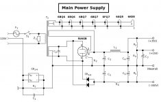
He's talking about something like this. Here, the main positive rail is derived from a 5U4GB. The negative rail uses silicon diodes to give a semi-symmetrical +/- power supply. It's one less hole to make, and the negative rail that provides the bias comes up before the main rail so that the finals are never running without bias. In this case, CRC filtration is more than adequate since the total current draw off the negative rail is just about 10mA.
Attachments
Hi,
One quick look at the original circuit and you know there have been made some bad choices:
-A 6SL7 won't drive a 2A3 unless it's configured as a CF
-Cathode decoupling tends to do exactly what you describe, slow, sluggish and dull.
Removing it will indeed speed up transient response put it also increases Zout, now your 6SL7 can't drive the the 2A3 even less and you'll have lost some of the gain.
I doubt you'll need all of it anyway but that's besides the point.
You could fiddle with the cathode resistor value but it won't do much for the inherent design flaw in the end.
- PS has too little capacitance, you'd need more F and fast film caps in the order of 50uF at the end to get things moving.
-Still not enough speed and want to stick with the circuit?
Use some small diameter silver wire to connect your stages.
Anyhow, not the best circuit to begin with....
Cheers, -😉
Hmm, probably best to forget direct coupling for now and use what you have. Actually Miles gives me too much credit, because what he posted is not exactly what I was thinking, it's better for this. It gets you a supply for the negative bias. That eliminates the cathode bypass resistor and cap. It will also increase your plate voltage, as you no longer have the cathode resistor in series with the tube. I would get rid of the series resistor in the power supply and instead, adjust the input cap to give you the voltage you want. Play with PSUD (look it up and download it. It's free).
Now, by adding just a couple of extra parts, and no new holes in the chassis, you can use your SN7 and still get plenty of drive. Look at this schematic: http://www.tubelab.com/TubelabSE.htm
If you use the FET follower (the 2sk device), you will have plenty of current to drive the 2A3.
As an option you can also use the current source instead of a plate resistor for the SL7. This will give you lower distortion too. Or you can keep the 100k plate resistor (If it were me, I might increase it to 150k or so, and increase the cathode resistor to around 2k). Either way you can eliminate the cathode bypass cap on the input tube and still have plenty of gain.
Sheldon
I just tried to remove all bypass caps and go from 6SL7 to 6SN7
Musicality improved a bit and i get a very detailed sound without becoming edgy.
I miss a little bit the gain of the 6sl7 (sound is now a little too "controlled" instead of "romantic and slow"). It may be the valve (electro harmonix)
I will also try to play with the PS caps (especially first), but have to spend a few $ if i want to try a PP caps PS.
I had tried SCR 2.2uF for first cap and removing all series resistors with a reasonnable B+ but the sound became just too slow.
Depending on what i have in stock, I will then try an electrolytic 40uF instead of PP 10uF for first cap.
For fixed bias : my power trans (hammond 302 ax) has in fact 300-0-50-300v taps. I guess i could make it dc with diodes between the 50v and 0v center tap and regulation caps ?
I tried now for the PSU
GZ34 -40uF - Choke10h - 40 uF - 1k - 100uF
all caps are electrolytics
5y3, according PSUD that i always use says me caps value is not compatible with cuurent forward repetitive maximum) then i used gz34
I have a little less sound quality especially details (electrolytics) ...but really more music...
I have sometimes found that the cheapeast components (a car radio for example or sometimes even mp3 on internet) made more music than my rig (but less sound), i mean i just understand the musical intent of performers better. But i always found radio to be a very musical source.
I often read than musicians especially dont need $$$ high end rig to get connected to music...i must agree than since i get into hifi sound it is a very distracting goal from the music. My wife always says i used to listen longer to music before, what i still do in my car... and i was my first hope building a diy tube amp.
so is it worth changing all caps to PP ? and which value depending on rectifer maximums : gz34 could be 60uf, 5u4 says 32 uf and 5r4 or 274b says 4uF...
I always use thin silver wire for all wires except earth sides.
- Status
- Not open for further replies.
- Home
- Amplifiers
- Tubes / Valves
- DHT and speed issues