Hello, I was hoping I could get some ideas on troubleshooting a Hafler DH-220. Actually the amp is a Smart Devices TA-242, but it is a DH-220 with a toroidal transformer basically. It uses the Hafler PC-19C boards and heatsinks.
I bought the amp off Ebay, untested from a recycler, so I have no idea of its history, etc.
I hooked it up to some inexpensive speakers and turned it on. Sound played from both channels, but the music was sort of thin and weak sounding. I figured that was just the way the amp sounded, and let it play for maybe 30 minutes while I did other stuff. When I went to turn the amp off, I noticed one of the heatsinks was HOT, the other a normal, slightly warm temp. I used my RS auto ranging DVM I’ve had for 10 years to check the bias current, but my meter gave me a weird reading and would slowly climb to out of range. I tried a free HF meter and got pretty much the same results. After that, neither meter gave correct results measuring anything, even continuity.
I decided to buy a good meter, so bought a Fluke 179 EDA2 kit and got it yesterday. Checked the bias on the amp again last night and got 240 mA on the left channel (spec is 275 mA), and when I checked the right channel I saw the meter display very quickly climb to 7.5 Amps before going offscale and showing “OL”, which the manual says is displayed when the meter is fed “over 20 Amps”. That was during the course of maybe a second or 2. I guess I know what happened to my other two “lesser” meters…..
I powered the amp back on for another few seconds and watched the 179 display. It seemed like the bias current wanted to try to stay around 700 mA, but would then spike to 3-4 Amps and higher, then come down, etc. The supply fuses are 8 Amps, so I assume the average current (or the peaks too short) must be less than that since the fuse didn’t blow when the amp was playing music.
I’m a mechanical engineer, so circuits aren’t my strong suit, and I’d appreciate any help I can get. I’ve already done a lot of researching, and I’m hoping it’s Q9 that is toast and causing this bias current issue. As best I can tell, I should be able to check the resistor leading to Q9 (amp powered off) and if it reads the right resistance then Q9 is open and toast.
I was hoping to get some responses with other things to check, so if I go check Q9 when I got home and that’s not the problem, I can test something else before going back to the internet to search.
Here’s an Audiogon post with pics of the amp:
Smart TA242 For Sale | AudiogoN
Here’s a link to the Halfer HD-220 manual:
http://www.hafler.com/techsupport/pdf/DH-220_amp_man.pdf
Here’s a link to the Smart Devices TA-242 manual:
http://www.smartdevicesinc.com/pdf/ta120-ta242.pdf
Thanks,
Mike
Took some measurements and this is what I found:
Good Channel
R22: 556
R23: 473
R24: 10.2
Bias Pot: 350
Bad Channel
R22: 472
R23: 463
R24: 10.2
Bias Pot: 430
I checked across every resistor using the good board as a reference, and R22 was really the only one that stood out. Using a magnifying glass I don't see any obvious cold solder joints, breaks, burns, etc anywhere.
Any ideas?
I have seen several Haflers with dead or dying bias generator transistors(q9)2n2222 or its equiv. cheap enough to replace and rebias.
Regards, Elwood
Regards, Elwood
Took some measurements and this is what I found:
Good Channel
R22: 556
R23: 473
R24: 10.2
Bias Pot: 350
Bad Channel
R22: 472
R23: 463
R24: 10.2
Bias Pot: 430
I checked across every resistor using the good board as a reference, and R22 was really the only one that stood out. Using a magnifying glass I don't see any obvious cold solder joints, breaks, burns, etc anywhere.
Any ideas?
You found the problem! Page 11 of the DH-220 manual states 275 ma as the proper bias current.
http://hafler.com/techsupport/pdf/DH-220_amp_man.pdf
Page 11 tells you how to pull the pos. fuse to the circuit card, put a meter across the fuse connections, and then dial back the bias current using P2.
You have a lucky find. Let me know if you want to sell one of the SMART amps 🙂.
The protective fuses on the rear are wired in series with the speaker output circuit and the thermal switches on the sinks, which is different from the stock Hafler. Check the schematic on page 14 of the manual.
Dick
Last edited:
Sorry, guess I should have been more clear. I was measuring the resistance of the bias pots, not the bias current in the measurements above. I think I took incorrect measurements though anyway; I was measuring from outside lead to outside lead on the pots.
I tried adjusting the bias pot to see what difference it makes, and the bias current goes berzerk (up into the 7 Amp+ range) when the pot is anywhere but fully counterclockwise. If I take it off the stop even a fraction of a hair, the bias current shoots back up to 7 Amps.
With the pot all the way on the counterclockwise stop I measured from either outer leg to center and it's reading about .5 (1/2) Ohms.
When measuring from the center leg to the leg closest to Q9, when you move the pot just off the stop the resistance jumps to about 8-10 kilo-Ohms range (8,000-10,000 Ohms) and the resistance much stays at this value anywhere you move the pot.
When measuring from the other leg to the center leg, the resistance stays at about .5 (1/2) Ohm, and doesn't change regardless of the position of the pot.
The other "good" channel shows about 490 Oms from center leg to the leg closest to Q9.
Don't know if it makes a difference, but when taking the bias current measurement (pot anywhere but on the stop), it may be somewhere in the 100's of mA for a second or two, then jumps up into the single Amps range, and you can hear the amp hum like it's pulling a lot of current. I've been switching it off as soon as it does this.
With the bias pot on the stop, the bias current reads about 20-30 mA, but the instant I move the pot off the stop, the current spikes in the single Amps range.
Is the pot toast, or is there more going on that I don't understand since the pot is still soldered in the circuit path? (Amp powered off for all these readings obviously)
Thanks,
Mike
I have a 470 Ohm resistor in my junk pile, if I leave the pot so it reads .5 Ohms and jumper the 470 Ohm resistor across the center pin to the pin closest to Q9 it should put the bias about right, correct?
The good channel measures 490 Ohms between these 2 legs to give a bias current of 275 mA.
Or will I fry something doing this?
This is just for testing so I can determine if the pot is bad, I'll replace the pot if this works.
Thanks,
Mike
The good channel measures 490 Ohms between these 2 legs to give a bias current of 275 mA.
Or will I fry something doing this?
This is just for testing so I can determine if the pot is bad, I'll replace the pot if this works.
Thanks,
Mike
Last edited:
Well the answer to my question would seem to be "yes", jumpering the pot (set off the stop in the Kilo-Ohm range) with a 470 Ohm resistor makes the amplifier bias approximately correctly.
The bias started out about 220 mA and climbed up to the low 230's mA over the course of a minute or so before I turned the amp off.
The reading wasn't that stable though; it would slowly climb for a while, then drop back down to 180-190 mA for a split second and jump back up to the 220's and keep climbing slowly, then drop down for a second again, etc.
Does this seem to indicate simply a bad trim pot, or is the non-steady current reading hinting at something else/also?
Are there different amp rating on tri pots, or will any 1K Ohm trim pot work for me?
Thanks,
Mike
Last edited:
You found the problem! Page 11 of the DH-220 manual states 275 ma as the proper bias current.
http://hafler.com/techsupport/pdf/DH-220_amp_man.pdf
Page 11 tells you how to pull the pos. fuse to the circuit card, put a meter across the fuse connections, and then dial back the bias current using P2.
Dick
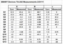
Beady, I am taking the liberty to put this conversation up here on the thread you started so that others may see/learn from your experiences, plus perhaps provide more expert advice than I can give. Also, attached is the measured table of values you just made and sent me in a private message. Others can examine your values and also compare them to the values printed in the Hafler D-220 manual. Here are my thoughts on your situation:
1. Beg, borrow or steal a Variac to use while you are trouble-shooting and repairing your amp.
2. Understand that the topology of this Hafler amp is dual complementary. The Pos side of the circuit is an almost mirror image of the Neg side of the circuit, and that measured values from similar and opposite parts of the circuit will be almost the same, but with reversed polarity.
3. Understand that a problem in the beginning of the circuit will distort voltages further down the line, so the place to start for repair is at the beginning of the circuit. The exception may be Q9 which may require replacement, or its present behavior may only be symptomatic of problems earlier in the circuit.
4. The first 4 small signal transistors (the two pairs Q3 and 4 -- Q5 and Q6) are the source of most problems with these amps. P1 can be adjusted to attempt to null out problems with DC offset, which you have. But, I believe your analysis is correct in that Q1 may be "toast." However, you have to measure voltages around Q1 and Q2, as P1 is adjusted, to determine if they can be made to be more mirror imaged (identical but of opposite polarity). Once that part of the circuit is repaired, you can determine if more work further down the circuit is required because the voltages in the remaining circuit are very dependent on the behavior of the Q1 and Q2 parts of the circuit. Ultimately, you should be able to use (P1) to adjust the collector voltages of Q1 and Q2 to be very similar.
5. Because this is a mirror image (complementary) circuit, the hFe of their complements should be very similar. The Q3,4 pair must have an identical (+/-) 10% match. Ditto the Q5,6 pair. And these corresponding pairs should be as similar as possible in their hfe. To get the close hfe matching for these 2 pairs of devices might require you to purchase 10-20 of each polarity to get the matched pairs required. There are on-line sources for the purchase of matched pairs if you do some investigating. This matching was very critical for the DH-200 which did not have the P1, Q1, Q2 circuitry for DC offset nulling. It is still important for the DH-220, but ultimate matching requirements are not quite as stringent.
6. Once the DC offset problem is corrected down to the base voltages of the Q7, Q10 pairs (with corresponding opposite polarities), re-measure the rest of the circuit and post your results here.
7. The output MOSFETs are very rugged and rarely cause a problem, unless massively abused. Although the driver pairs (q7,8 and Q10,11) sometimes cause problems their troubleshooting is simpler than the first part of the circuit.
8. Precise voltage matchings can be tricky and repair difficult to get them exactly as in the Hafler table of voltages because the feedback circuit can correct (or mask), to a degree, for some voltage irregularities. To what percentage I don't know, but if you get the final output DC offset down to below 30 mV your should be OK.
Now, let the flames begin as those more expert than me may have some corrective statements. However, that is the way we all learn. But, get a Variac for your repair!
Good luck. I will watch for further postings at this thread.
Attachments
I think I have successfully repaired the amplifier.
I desoldered the faulty bias pot and Q1, as I believed Q1 was bad. However, testing Q1 out of the circuit using my DMM in diode mode showed that Q1 tested good. I had clipped the leads of Q1 removing it, so I had to wait for my replacement to arrive.
After soldering in a new bias pot I got to thinking about Q1 not being bad, and what the readings I had taken when it was installed meant. I went back and educated myself on how transistors operate (it’s been going on 20 years since I had a circuits class), and I realized that the zero voltage on the base likely meant that Q1 wasn’t getting a signal to that leg, not that it was toast. Now, I knew I had checked all the diodes and resistors on the board, and they checked good, but it seemed that an open diode or resistor between the input and Q1’s base was the most likely culprit.
I rechecked everything from the input to Q1 and all the components checked Sat. I sat there and stared at the schematic for a long while, trying to figure out what could be going on, when it struck me that the only “resistor” that I had not checked was the offset pot. I had checked it before, but apparently had only checked the leg that pointed away from Q1, because when I measured from the center leg to the leg pointing to Q1, I got a reading in the hundreds of Kilo-Ohms, no matter the position of the wiper.
After replacing Q1 and the offset pot, I was able to dial out the DC offset (to under 10 mV), and set the bias to 275 mA +/- 1, after the amp had warmed up for half an hour. The amp has probably 8-10 hours of time playing music on it now, and it seems to be behaving.
I did build a dim-bulb tester to use when powering up the amp again.
Thanks for the help and comments to those who replied.
Here is the link to my other related post:
http://www.diyaudio.com/forums/soli...t-adjust-dc-offset-using-offset-bias-pot.html
Maybe this info will help someone in the future.
Mike
I meant to say since there was no signal at the collector, there must not have been a signal present at the base.
Another DH-220 Offset problem
Dick,
Thanks for this great post. I'm a total newbee to electronics, but am trying to repair 2 DH-220's I purchased from different sources on eBay. My intent is to bridge each one to run as mono amps, but before bridging, I checked the bias and DC offset. On one amp, I was easily able to set the Bias on both channels to .27 A (my meter won't give me the third digit, so 270 mA is as close as I can get to spec of 275 mA). I was also able to set the Offset on the LEFT channel (measured at the output 5-way speaker posts with the amp ON) to 0 V, with the voltage fluctuating up and down through +2.8 mV, but not going negative.
1. Is this fluctuation normal?
On the RIGHT channel, I was only able to get down to 206 mV with the P1 pot at the full CCW stop. I have cleaned P1 with LPS Electro Contact Cleaner to no affect, and have checked the resistance of surrounding R4 & R5 and R6 & R7, and all are VERY close to their banded values.
I have not checked the transistors since I’m not sure exactly how to proceed. I read in the Hafler DH-220 Manual to test each leg (collector, base, emitter) “…with 120 volt line, no signal, with respect to the ground buss between the two capacitors in the power supply.”
2. I assume this means with the amp ON, and my tester’s black lead should be connected to the ground wire connecting the two big 10k mfd filter caps (C403, C404) while I touch the red lead to each of the transistor legs I am testing?
3. Also, the only pictogram of the PC-19C board I can find is in the afore-mentioned manual downloaded from the hafler website, but it has a digital glitch across the top part of the board, nulling some of the labels. Can you please check the attached pdf with my assumptions and let me know if they are right?
4. Finally, from your above quoted post, I gather that proper diagnosing of the transistors on these amps is to start at the beginning of the circuit and work your way through, as errant values at the beginning affect the values of later components (makes sense). From what I can tell, this would be pretty much working from the top of the board toward the bottom, from Q1 through to Q13. And, that most of the transistors work in match pairs (Q3 & Q4; Q5 & Q6; Q7 & Q8; Q10 & Q11) and should be replaced in matched pairs (this from reading on the forums and looking at the voltage chart at the bottom of page 12 of the manual). Is this correct?
Any responses would be GREATLY appreciated. Once I get this amp in shape, I will post problems with a right channel buzz in the other amp. Thanks!
mark
Beady, I am taking the liberty to put this conversation up here on the thread you started so that others may see/learn from your experiences, plus perhaps provide more expert advice than I can give. Also, attached is the measured table of values you just made and sent me in a private message. Others can examine your values and also compare them to the values printed in the Hafler D-220 manual. Here are my thoughts on your situation:
1. Beg, borrow or steal a Variac to use while you are trouble-shooting and repairing your amp.
2. Understand that the topology of this Hafler amp is dual complementary. The Pos side of the circuit is an almost mirror image of the Neg side of the circuit, and that measured values from similar and opposite parts of the circuit will be almost the same, but with reversed polarity.
3. Understand that a problem in the beginning of the circuit will distort voltages further down the line, so the place to start for repair is at the beginning of the circuit. The exception may be Q9 which may require replacement, or its present behavior may only be symptomatic of problems earlier in the circuit.
4. The first 4 small signal transistors (the two pairs Q3 and 4 -- Q5 and Q6) are the source of most problems with these amps. P1 can be adjusted to attempt to null out problems with DC offset, which you have. But, I believe your analysis is correct in that Q1 may be "toast." However, you have to measure voltages around Q1 and Q2, as P1 is adjusted, to determine if they can be made to be more mirror imaged (identical but of opposite polarity). Once that part of the circuit is repaired, you can determine if more work further down the circuit is required because the voltages in the remaining circuit are very dependent on the behavior of the Q1 and Q2 parts of the circuit. Ultimately, you should be able to use (P1) to adjust the collector voltages of Q1 and Q2 to be very similar.
5. Because this is a mirror image (complementary) circuit, the hFe of their complements should be very similar. The Q3,4 pair must have an identical (+/-) 10% match. Ditto the Q5,6 pair. And these corresponding pairs should be as similar as possible in their hfe. To get the close hfe matching for these 2 pairs of devices might require you to purchase 10-20 of each polarity to get the matched pairs required. There are on-line sources for the purchase of matched pairs if you do some investigating. This matching was very critical for the DH-200 which did not have the P1, Q1, Q2 circuitry for DC offset nulling. It is still important for the DH-220, but ultimate matching requirements are not quite as stringent.
6. Once the DC offset problem is corrected down to the base voltages of the Q7, Q10 pairs (with corresponding opposite polarities), re-measure the rest of the circuit and post your results here.
7. The output MOSFETs are very rugged and rarely cause a problem, unless massively abused. Although the driver pairs (q7,8 and Q10,11) sometimes cause problems their troubleshooting is simpler than the first part of the circuit.
8. Precise voltage matchings can be tricky and repair difficult to get them exactly as in the Hafler table of voltages because the feedback circuit can correct (or mask), to a degree, for some voltage irregularities. To what percentage I don't know, but if you get the final output DC offset down to below 30 mV your should be OK.
Now, let the flames begin as those more expert than me may have some corrective statements. However, that is the way we all learn. But, get a Variac for your repair!
Good luck. I will watch for further postings at this thread.
Dick,
Thanks for this great post. I'm a total newbee to electronics, but am trying to repair 2 DH-220's I purchased from different sources on eBay. My intent is to bridge each one to run as mono amps, but before bridging, I checked the bias and DC offset. On one amp, I was easily able to set the Bias on both channels to .27 A (my meter won't give me the third digit, so 270 mA is as close as I can get to spec of 275 mA). I was also able to set the Offset on the LEFT channel (measured at the output 5-way speaker posts with the amp ON) to 0 V, with the voltage fluctuating up and down through +2.8 mV, but not going negative.
1. Is this fluctuation normal?
On the RIGHT channel, I was only able to get down to 206 mV with the P1 pot at the full CCW stop. I have cleaned P1 with LPS Electro Contact Cleaner to no affect, and have checked the resistance of surrounding R4 & R5 and R6 & R7, and all are VERY close to their banded values.
I have not checked the transistors since I’m not sure exactly how to proceed. I read in the Hafler DH-220 Manual to test each leg (collector, base, emitter) “…with 120 volt line, no signal, with respect to the ground buss between the two capacitors in the power supply.”
2. I assume this means with the amp ON, and my tester’s black lead should be connected to the ground wire connecting the two big 10k mfd filter caps (C403, C404) while I touch the red lead to each of the transistor legs I am testing?
3. Also, the only pictogram of the PC-19C board I can find is in the afore-mentioned manual downloaded from the hafler website, but it has a digital glitch across the top part of the board, nulling some of the labels. Can you please check the attached pdf with my assumptions and let me know if they are right?
4. Finally, from your above quoted post, I gather that proper diagnosing of the transistors on these amps is to start at the beginning of the circuit and work your way through, as errant values at the beginning affect the values of later components (makes sense). From what I can tell, this would be pretty much working from the top of the board toward the bottom, from Q1 through to Q13. And, that most of the transistors work in match pairs (Q3 & Q4; Q5 & Q6; Q7 & Q8; Q10 & Q11) and should be replaced in matched pairs (this from reading on the forums and looking at the voltage chart at the bottom of page 12 of the manual). Is this correct?
Any responses would be GREATLY appreciated. Once I get this amp in shape, I will post problems with a right channel buzz in the other amp. Thanks!
mark
Attachments
- Status
- Not open for further replies.
- Home
- Amplifiers
- Solid State
- DH-220 Clone (SMART TA-242) WAY too high bias current issue?