http://www.alltronics.com/download/1373.pdf
Have a look on page 1.
The diagram shows a charge pump and a bootstrap, they only show a "boot" cap the rest is internal.
Typically on driver IC's that have both, the bootstrap does the grunt work and the charge pump is only there to maintain the bootstrap's charge so that it can be used for very large duty ratio's/low frequency or whatever.
Me again with the reverse recovery issue. 🙄
There are circuit topologies that don't know reverse recovery at all since they avoid the diodes going into reverse conduction.
One solution has been proposed by Brian Attwood and it was used in the Peavey DECA series amps.
Regards
Charles
There are circuit topologies that don't know reverse recovery at all since they avoid the diodes going into reverse conduction.
One solution has been proposed by Brian Attwood and it was used in the Peavey DECA series amps.
Regards
Charles
Hi,
You mean DirectFet?
There have been others which claimed to cure this too and they didn't.
It would be a shame to have to restrict topology just to avoid that. BCA might be one but it has other issues.
A strong driver is required.
Tripath's patents are usually vague, do they go into any detail about that?
US5408150 is worth a read.
Some designers place a Schottky diode in series with each MOSFET to prevent body diode forward biasing. I have not done much simulation and even less physical experimentation concerning that technique.
Charles,
Yesterday it finally occurred to me how to delay a pulse wave, phase shift it, without shortening the on-time. It is for my SMPS design, so I think it would not work as well for class D since the resistor, for variable delay, would be replaced with something like an H11Fx bidirectional FET output optoisolator due to the fact that the resistor sees dual polarity. It is possible to insert a transistor inside a bridge rectifier where the resistor goes, but the results suffer.
Attachments
Oops, the phase shifter above works on the simulator because the input gates do not include the over-voltage protection shunt diodes. In real life, those diodes dissipate some of the charge on the capacitor, decreasing the on-time and ruining the duty cycle preservation. The result is that the greater the resistor and attempted phase shift, the worse the problem.
subwo1 said:
Indeed, reverse breakdown can cause internal hot spots and then failure.
I didn't mean by diode failure--I mean GATE failure.
Note: I didn't connect the bootstrap cap -- some diagram has it unconnected,and I didn't know what is it for.
Nice tweak for the upper driver is put a cap on it with a diode over it, it'll pump the gate below zero and provide about a volt of negative bias.
Sadly, it only works on the upper driver
Sadly, it only works on the upper driver
N+P bridge is more simpler,but the P-channel FET has an Ron more larger...unsymmetric and low current capability.
use a full bridge can get back the symmetry and have higher power output.
is it worthy to use a N+P design,with a transistor gate driver instead of chip,and use the saved cost to build a full bridge?
full bridge could also simplify the PSU,and use a smaller filter cap.
which design have less overall cost?
Kenshin said:N+P bridge is more simpler,but the P-channel FET has an Ron more larger...unsymmetric and low current capability.
use a full bridge can get back the symmetry and have higher power output.
is it worthy to use a N+P design,with a transistor gate driver instead of chip,and use the saved cost to build a full bridge?
full bridge could also simplify the PSU,and use a smaller filter cap.
which design have less overall cost?
I think it would be very difficult to properly do a reliable full bridge with an ordinary discrete bjt driver. It is difficult enough to get one working with a half bridge and symetric N channel switches, and as you say, P channels will be slower to respond.
High power P channels are also still alot more rare than N channels and are more expensive than N channels, so I don't really see where you're saving in cost. I think the usual practice is to oversize the P channel with respect to the N channel as well, as an attempt to try and match Ron. Therefore you'd need an even more expensive mosfet.
I'll confirm this in a few minutes, but I think it takes transistors to drive a high side N channel as well!
I think all you save with a P channel is the bootstrap circuit, which isn't substantial by any means.
It seems it is best to use dual LC filters in full bridge as well (better rejection of common mode signals), so you dont' get away with a smaller cap, but require another identical one.
Less overall cost? With the circuit I worked on before (full bridge) it only doubles the output stage (drivers, boostrap/supply, mosfets and filter).
So that's not alot of added cost! Also, you can design a full bridge to handle 4X the power of a a similar half bridge.
In that respect the PSU isn't really simplified, but you can use smaller and far cheaper parts for it than a similar half bridge design would require (to achieve the same power level that is). Since things like PSU toroidal transformers and large can electrolytics of high quality are big ticket expensive items, this would be a substantial savings!
So with that in mind, my opinion, for any given power level, a full bridge would pay for itself, and is well worth doing.
However a robust/precise driver is likely even more important.
classD4sure:
In the robocon race we use the IRF540 N-FET and IRF9540 P-FET(without oversize) full bridge to drive our motors, two FET have almost the same cost. And the gate driver is also simple and reliable.So I consider modify the motor driver board - it has been tested by many users - into an audio one.
In the robocon race we use the IRF540 N-FET and IRF9540 P-FET(without oversize) full bridge to drive our motors, two FET have almost the same cost. And the gate driver is also simple and reliable.So I consider modify the motor driver board - it has been tested by many users - into an audio one.
Kenshin said:classD4sure:
In the robocon race we use the IRF540 N-FET and IRF9540 P-FET(without oversize) full bridge to drive our motors, two FET have almost the same cost. And the gate driver is also simple and reliable.So I consider modify the motor driver board - it has been tested by many users - into an audio one.
Hi,
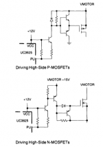
Discrete methods for driving both high side P and N channel fets...
has the same part count.
Sounds like a good idea I'd go for it, it can work of course.
What kind of robot did you build anyway? I made a maze crawler before, I stole parts off it to make my amp too.
At least with a P channel you probably wont' get that regenerative affect either.
Attachments
ClassD4sure:
The robots we build are for USTC school robot race "robogame" and for Asia Broadcasting Union's Asia-wide race "Robocon". The biggest motors we used have a power ratings around 24V 3A, and the starting current is probably up to 10A.
what's the chip appearing in your schematic ?
The robots we build are for USTC school robot race "robogame" and for Asia Broadcasting Union's Asia-wide race "Robocon". The biggest motors we used have a power ratings around 24V 3A, and the starting current is probably up to 10A.
what's the chip appearing in your schematic ?
Hi,
Yeah I've got motors like that that do 50K rpm!
According to the picture, it's a UC3625, brushless DC motor controller.
I copied that out of it's data sheet
So,
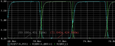
I tried a little modification to the gate drive.
What do you guys think of these drive signals??
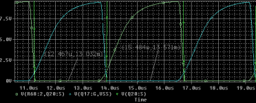
Here is the before:
Yeah I've got motors like that that do 50K rpm!
According to the picture, it's a UC3625, brushless DC motor controller.
I copied that out of it's data sheet
So,
I tried a little modification to the gate drive.
What do you guys think of these drive signals??
Here is the before:
Attachments
Since things like PSU toroidal transformers and large can electrolytics of high quality are big ticket expensive items, this would be a substantial savings!
A quick shot from the hip lets one think that. But if you have a closer look then you see that you need about the same amount of PSU capacitance and the same voltage rating for your electrolytics when using a half-bridge topology. The only disadvantages of half-bridge are larger Vds and supply pumping IMO.
Regards
Charles
phase_accurate said:
A quick shot from the hip lets one think that. But if you have a closer look then you see that you need about the same amount of PSU capacitance and the same voltage rating for your electrolytics when using a half-bridge topology. The only disadvantages of half-bridge are larger Vds and supply pumping IMO.
Regards
Charles
pumping effect means bigger electrolytics is needed.
full bridge have a PSU current frequency doubled than the audio signal, so the big electrolytics could be half the size.
also,half bridge is more sensitive on PSU unsymmetry and PSU flucations.If full bridge is robust enough, we could use a SMPS--it's more cheaper.
overcurrent / overvoltage protection may also be simpler.
aaaaaaand the after~!
Charles, thanks for correcting me, you are quite right.
I'm not sure if you'd save on the transformer either, cost goes up by VA rating but independant of voltage I think.... so it would likely cost more.
I still think it would be worth it to get away with a lower Vds.
Charles, thanks for correcting me, you are quite right.
I'm not sure if you'd save on the transformer either, cost goes up by VA rating but independant of voltage I think.... so it would likely cost more.
I still think it would be worth it to get away with a lower Vds.
Attachments
Maxim/Dallas has produced some full bridge chip class-D amplifiers which can be powered directly by a "dirty" SMPS for logic circuits and send out a voice signal with 0.03%(typical) THD. that's nice.
the protection problem is another major reason I favoured the full bridge : +/- PSU means doubleing the whole protect circuit.
power diode to prevent foolish PSU connect
Current-sensing resistor
Reuseable electronic fuse--some users often replace the blown fuse with iron screw, so general fuse isn't safe enough for a commercial module (if massive producted).
TVR devices(or SCR) to short the rails and blow the fuse during serious overvoltage
These additional complexity and cost may be able to buy another pair of FETs
Kenshin said:Maxim/Dallas has produced some full bridge chip class-D amplifiers which can be powered directly by a "dirty" SMPS for logic circuits and send out a voice signal with 0.03%(typical) THD. that's nice.
the protection problem is another major reason I favoured the full bridge : +/- PSU means doubleing the whole protect circuit.
power diode to prevent foolish PSU connect
Current-sensing resistor
Reuseable electronic fuse--some users often replace the blown fuse with iron screw, so general fuse isn't safe enough for a commercial module (if massive producted).
TVR devices(or SCR) to short the rails and blow the fuse during serious overvoltage
These additional complexity and cost may be able to buy another pair of FETs
I am glad you mentioned these things about SMPS design characteristics. The problem of DIYing these types of supplies so as to lessen radiated and conducted noise is why I am working on the design of a couple of zero voltage switching (ZVS) approaches. I am still in the simulation stage of the process as of now.
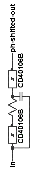
Several posts back, I displayed an image of a phase shift modulator to be used in a bridge version of one of the circuits that I am working on, but I learned that the input protection diodes of the CD40106B ( 74C14) were clipping off some of the charge on the phase shift capacitor, throwing off balance in the duty cycle.
Now, it finally came to me, correctly this time I think, that removing some of the voltage from the phase shift resistor using a voltage divider could even out the mark/space timing by compensating for the charge lost from the capacitor. Possibly, a single voltage divider resistor could work in series with a capacitor, but the two resistors placed across the power supply should be better in most cases.
Attachments

- Status
- Not open for further replies.
- Home
- Amplifiers
- Class D
- Development of a "reference" class D starting point