You call that big?? You know I built this with no scope, right?
It's 35 watts and loud enough to make the landlord complain.
The heatsinks stay _cold_. In that respect yeah they're bigger than they need to be, but it took alot of scopeless tweaking to get it there. I cut them out of an old ACER monitor. They work.
It's 35 watts and loud enough to make the landlord complain.
The heatsinks stay _cold_. In that respect yeah they're bigger than they need to be, but it took alot of scopeless tweaking to get it there. I cut them out of an old ACER monitor. They work.
Thought I'd test a few things out just to note their worth.
I improved the decoupling on my homebrew amp and added snubbing.
I don't think I'm imagining an improvement here, it can still be better with respect to noise floor, but there's no FM reception (which occured after I slapped in a pair of 470uF caps half hazardly).
I believe I give full credit to the snubber for the change in character the sound has taken. It's still got all the characteristics it had before only now the phase of the small fast stuff, such as natural delays, echo's, reverb etc, seems well preserved. I realize only now they were smeared before.
It seems to help in creating an ultra lifelike sound. Piano's sound perfectly natural, same with orchestra, can pick out every back up singer and envision where each stands beside each other, that sorta thing.
Everything is much tigher and more controlled, doesn't feel too fast but now see it was overly relaxed before.
Overall the improvement on dynamic range across the band also seems significant.
Oh, I'd like to add it's not imagined because wherease before there were certain songs too complex for it to sound good on, they weren't enjoyable. I've played them all and that's where it was the most impressive because they're all very enjoyable now.
Can you think of anything you might improve upon in either of your circuits?
Not at this moment. I draw 300wats out of the Voltage feedback configuration with FDD3682 (Fairchild) Moefets on a -/+37V supply with a 2ohm load. The THD is arround 0.1% depending on the amout of local decoupling and print layout.
I'm working on additional PID control (feedback) for the amp. In simulations i can supress errors with ~35dB at 10kHz and more at lower frequencys if preferred (however this gives a non-flat THD response, witch is usually not preferred).
In theory this will result in 0.1%/10^(35/20)=0.002% THD. I don't expect to reach this, but just 20dB of improvement will result in 0.01%THD, wich is pritty good too.
All this can be done with one opamp for a non-inverting configuration and two with an inverting configuration. I prefer the invertin configuration, since the commen mode compenent is almost zero => best possibility to get a good THD figure. I plan to use MAX4489 opamps.
By the way the dynamic range without PID feedback is 120dB+. I can't mesure that the amp is turned on with my soundcard with has 120dB dynamic range and I'm still able to saturate the soundcard.
Throwing feedback at the problem is like taking polluted water, and adding chemicals to balance out the acidity, and kill the bacteria. The water will be technically clean, but would you drink it?
Why not keep the water clean, or the audio signal free from THD in the first place? It is perfectly possible to make 0.002% THD without any feedback loops, a part from the single integrator loop.
All the best from
Lars Clausen
Why not keep the water clean, or the audio signal free from THD in the first place? It is perfectly possible to make 0.002% THD without any feedback loops, a part from the single integrator loop.
All the best from
Lars Clausen
Reaching .002% really without feedback it is very expensive and impractical approach, and troubles will rise with power (maybe ^2). Even so fast&accuracy switching chip as TDA8939, will produce .05% at 50w@300khz, i guess. PID -well famous, cheap and absolutely natural control method, why we can't use it successfully?
Hello IVX: I am sorry, i am sure everybody who have followed this thread, know what you mean by the term PID? Please explain.
I feel a little bit silly, because lately i didn't have so much time to go on the forum and follow the many interesting threads. I have been working in the lab, on solving some of the last remaining fundamental problems in constructing Class D amplifiers on a higher performance level. I must say it's amazing how far you can go, when you have full time, and plenty of funds to work with. During the last 5 years i have collected of course a lot of practical experience, and knowledge about the amplifier / speaker interface, and sound / specs relationship. But i never felt i had the time to really go in depth with solving the more complex technical challenges. So now i feel lucky to be able to complete this technical ground work, and really investigate the phenomena i only had time to observe before. I hope this explains my lack of up-to-date ness on the discussions here on the forum 🙂
All the best from
Lars
PID = proportional integral derivative.
Not to stray too much off topic, but I wonder if Lars or anyone else has quantified the statistics of the noise in the creation of the conducting channel of a typical power MOSFET?
I know the body diode charge is a messy variable as well.
Not to stray too much off topic, but I wonder if Lars or anyone else has quantified the statistics of the noise in the creation of the conducting channel of a typical power MOSFET?
I know the body diode charge is a messy variable as well.
I've build an amp based on the schematis I've posted earlier in this thread (page 55). Additionally short circuit protection has been added, to prevent failure.
It's build of 95% smd components and all hand made, even the pcb.
The losses are quite low. Each mosfet dissapates >1W at zero output and a few watts at full load.
The modulation is done kinda Mueta.
Switcing amp review 9:
It's build of 95% smd components and all hand made, even the pcb.
The losses are quite low. Each mosfet dissapates >1W at zero output and a few watts at full load.
The modulation is done kinda Mueta.
Switcing amp review 9:
An externally hosted image should be here but it was not working when we last tested it.
What about losses in the output filter inductor? Looks to me like a standard Toroid? In my experience the losses here are too high.Is there an air gap?
What is the switching freq??
By the way can you be specific about the post number where the schematic was and not the page number.
If you refer to the post number, when you say page number, it is probably wrong. There is a schematic in post #54 though.
Koldby
What is the switching freq??
By the way can you be specific about the post number where the schematic was and not the page number.
If you refer to the post number, when you say page number, it is probably wrong. There is a schematic in post #54 though.
Koldby
sovadk said:I've build an amp based on the schematis I've posted earlier in this thread (page 55). Additionally short circuit protection has been added, to prevent failure.
It's build of 95% smd components and all hand made, even the pcb.
The losses are quite low. Each mosfet dissapates >1W at zero output and a few watts at full load.
The modulation is done kinda Mueta.
Hi sovadk
It looks very neat, very well done and with just a few watts of heat dissipation.

Do you know the frequency response and distortion figures?

Well done
Sovadk,
Very nice, my compliments, I'm still playing with perf. board myself. To add to the post above mine, how about some performance and distortion figures? I'm sure we'd all like to know what your amplifier is capable of.
Best regards,
Sander Sassen
http://www.hardwareanalysis.com
Very nice, my compliments, I'm still playing with perf. board myself. To add to the post above mine, how about some performance and distortion figures? I'm sure we'd all like to know what your amplifier is capable of.
Best regards,
Sander Sassen
http://www.hardwareanalysis.com
To koldby
The schematic is in post #544.
The loss in the output inductor is very small. The series resistance is arround 20mohm which gives 1W dissapation with 200W into 4ohm. The core is Micrometals T106-2 wich has a very low loss. For this application the matrial of this core is outstanding, however the permittivity quite low, so it requires ~40 tuens for 22uH. According to Micrometals design software the core loss is 0.44W @ 200W into 4ohms. I haven't noticed any real temperature rise of the inductor, even under high load conditions.
The real reason why I chose this core was because of it's linearity and availability @ ebay.
The siwtcing frequency is ~300kHz.
T106-2 @ Micrometals
To KLe and SSassen
Thanks for the comments.
The distortion is arround 0,1%, but the mesurement is from an earlier review, so I can't really tell. I've done simulations with added PID feedback, which can supress errors further by 35dB @ 10kHz and more at lower frequencys if desired. Theorytically this should give a distortion figure of 0.002%.
About the frequency responce. According to simulations it should be totally flat and load independent, wiht a bandwidth of 60kHz. I haven't done any mesurements to confirm this.
Right now I'm on holliday, so I'm unable to do semething about it.
Hi Sovadk,
Do you have problem with symmetric output? I simulate your amp and found that the output is not balanced. I see also that your high side gate without resistor. It may because the high side gate turn on lately than low side gate.
Is there no problem with that?
Thanks, happy holiday.
Do you have problem with symmetric output? I simulate your amp and found that the output is not balanced. I see also that your high side gate without resistor. It may because the high side gate turn on lately than low side gate.
Is there no problem with that?
Thanks, happy holiday.
I have experinced some DC supply pumping which increeses with the output load. This causes increesed distortion and higher supply voltage which can be critical (breakdown voltage might be reached).
The reason why the unsymmetry has an affect, is because of the low gain of the hysteresis comperator. The gain af a hysteresis comperator is determined by the ratio between the two resistors that sets the hysteresis voltage. The means that the gain in my case is only about 40dB, which causes a voltage difference on the two comperator inputs and from this a DC voltage at the output.
A solution could be to slow down the low side driver, however I epect this problem to disappear with additional feedback.
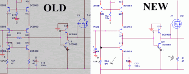
I've changed the comperator a bit, to speed up the output transition from low to high (see the picture attached). This helps a bit.
The new resistor in series with the source of X1 protects the mosfet from failure. I use 56ohm currently.
The reason why the unsymmetry has an affect, is because of the low gain of the hysteresis comperator. The gain af a hysteresis comperator is determined by the ratio between the two resistors that sets the hysteresis voltage. The means that the gain in my case is only about 40dB, which causes a voltage difference on the two comperator inputs and from this a DC voltage at the output.
A solution could be to slow down the low side driver, however I epect this problem to disappear with additional feedback.
I've changed the comperator a bit, to speed up the output transition from low to high (see the picture attached). This helps a bit.
The new resistor in series with the source of X1 protects the mosfet from failure. I use 56ohm currently.
Attachments
I like your amp.
Your amp arrangement support high speed switching because no need holding current, t-on and t-off can be fastly.
After try the UCD based, I will try your amp. I think your amp did not need very high grade component to support the speed.
Isn't?
The other, your amp is very simple in control the turn on-off time. No many component that have contribution in on and off time.
But if you add a resistor to the drain of mosfet as picture, you probably still have 1 to 2 volt at OFF state at high side driver. What is the voltage treshold of your ON state of your mosfet?
Thanks and congratulation finally.
Sovadk,
I am not able to see your sch. at post #544, could you re-send it?
I'd like to see how did you solve the overcurrent protection also, and if it is short-circuit proof as well.
Good work!
Pierre
I am not able to see your sch. at post #544, could you re-send it?
I'd like to see how did you solve the overcurrent protection also, and if it is short-circuit proof as well.
Good work!
Pierre
Thanks for the feeback.
To kartino
You're right, there's no need for high grade components. BC8?6 or similar will do just fine. The gate drive BJT's dosn't have to be high current ones, like I've chosen. The real critical component is the mosfet for the high side driver. I haven't found the right one yet.
The MOSFET's I'm using (FDD3682) has a thresholdvoltage of 3,2V @1mA (my own mesurement. Taking into account the voltage across the driver BJT, theres 3.2V + 0.6V -12V*56ohm/390ohm=~1.8V of space. It might be pushing it, you tell me.
To Pierre
The schematic is suddenly gone from post #544, so here you have it again (attached below).
I might post the short circuit protection later. Right now I'm on holliday, so I don't have acces to my files.
It's simple, very fast and discrete. It might have some problems with supplyrejection though, which can cause it to trigger. I'm testing that IRL currently.
Attachments
Hi Sovadk,
Happy holiday for you.
If you solve your problem I believe that your amp will be fastest ever for discrete class-d, no critical setting, and possibility to upgrade to the higher power level.
Keep go on.
br/kartino
Happy holiday for you.
If you solve your problem I believe that your amp will be fastest ever for discrete class-d, no critical setting, and possibility to upgrade to the higher power level.
Keep go on.
br/kartino
- Status
- Not open for further replies.
- Home
- Amplifiers
- Class D
- Development of a "reference" class D starting point