Charlie, I tried signing up to that other forum you mentioned about a week ago.
But after five or so tries all failing I left. I think I saw something where you were
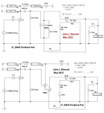
trying NFB from the OPT secondary to your 6N6G cathode.
For sure that can & is done either alone or with other FB paths.
So I stuck that into your circuit while running an OPT of 7K_8R.
The calcs shew a DF of 0.88, not a lot but for sure better than the bare bones cct.
With 2V in at the 27 grid the output is 2.6W
At 2.5V in the output is 4.1W, about the limit for the 6N6G in this kind of cct.
There are an infinity less one ways to arrange these things.
I've something else to send in a couple of daze after I get out from under
some other work here.
But after five or so tries all failing I left. I think I saw something where you were
trying NFB from the OPT secondary to your 6N6G cathode.
For sure that can & is done either alone or with other FB paths.
So I stuck that into your circuit while running an OPT of 7K_8R.
The calcs shew a DF of 0.88, not a lot but for sure better than the bare bones cct.
With 2V in at the 27 grid the output is 2.6W
At 2.5V in the output is 4.1W, about the limit for the 6N6G in this kind of cct.
There are an infinity less one ways to arrange these things.
I've something else to send in a couple of daze after I get out from under
some other work here.
Attachments

Thanks, John . . . Just to clarify, the build thread on Audio Karma that I linked earlier uses cathode feedback with a SE 6BQ5 amp not with a 6N6G. Since I was running the 6BQ5 in pentode I figured it needed some NFB since the remote preamp section that the amp originally used was missing.Charlie, I tried signing up to that other forum you mentioned about a week ago.
But after five or so tries all failing I left. I think I saw something where you were
trying NFB from the OPT secondary to your 6N6G cathode.
For sure that can & is done either alone or with other FB paths.
So I stuck that into your circuit while running an OPT of 7K_8R.
The calcs shew a DF of 0.88, not a lot but for sure better than the bare bones cct.
With 2V in at the 27 grid the output is 2.6W
At 2.5V in the output is 4.1W, about the limit for the 6N6G in this kind of cct.
There are an infinity less one ways to arrange these things.
I've something else to send in a couple of daze after I get out from under
some other work here.
Not sure why you had a problem registering at AK, you might want to try again sometime. It's typically less technical than DIY, although there are certainly some very knowledgeable members. For example, Dave Gillespie, who developed the EFB (Enhanced Fixed Bias) scheme, suggested the cathode FB circuit I'm using with the SE 6BQ5.
You should be able to view threads on AK, though, even if you aren't registered.
Also, my "inverted SET" (iSET) 6N6G amp, which I've dubbed the Nuance, uses a 26 on the input. Jeff, who started this thread, has been using the 27 in his build, although he's said he may try some others. It's my understanding that the 26 and 27 are pretty much the same electrically, though.
When building the Nuance, I took your advice and connected the plate of the input section of the 6N6G to the plate of the output section. As I mentioned, the sonic results are what you would expect to hear with NFB.
Would you characterize this as NFB? If so, since it's plate to plate, would it be considered Schade?
Perhaps it's not considered NFB because the input section is configured as a cathode follower and not a voltage amplifier, as a "normal" input tube would be. (??)
Whatever it is, it works well.
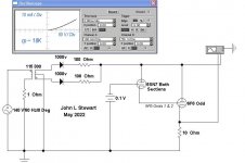
In last nights Sim I wanted to shew how the 6N6G you are using would do with OPT secondary to power tube cathode NFB.
Looks like it helps some with the DF. A simple fix, sometimes that is all that is needed.
Connecting the input plate to the output plate of the 6N6G is the same as triode strapping any of the common power pentodes.
In the data sheets covering many power pentodes both modes of operation are often listed & the plate/grid plots shewn.
If a 6N6G were plotted with its plates tied together it would simply look like any common triode.
But there are some folks who do put forth an argument that it is a form of NFB.
I've got an old technical paper (not mine) on file here somewhere covering that,
I'm not sure why the 26, 27 & 30 are so popular in these amps of the present era. I see no advantages & plenty of problems.
But the 30 makes a great regen detector, even when running at 22.5V of B+. With some olde headphones & 100 feet
of outdoor antenna. With a lightning arrestor too!
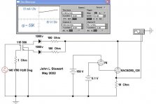
So this AM I've put a simple alternative together that will make your 6N6G sing like it was meant to do.
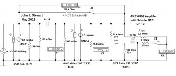
The front end is a 6SJ7 sharp cutoff pentode. That gets some gain so that Schade NFB can be used.
The rest of the amp remains the same. The 6SJ7 could just as well be a 6J7, 6C6, 77 or 57 with a slight reduction in the final DF.
The resulting amp has about 14.35 db Schade NFB & DF is greater than 3. Full 4W is possible with just 2.5V RMS at the front end.
The sim in this case is still in the form I would have used as a first pass to check if the design was worth going forward with.
The gain of each part is shewn in one Sim along the bottom & based on the no FB condition switch 'A' open.
The other Sim shews the condition while Schade NFB is connected.
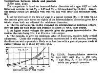
Some people are allergic to using pentodes here on DIY. But look at the comparative results from RDH4 running
a 6J7 in pentode vs triode modes. Up to a certain level the pentode mode is better in terms of distortion.
NFB back to the plate of a triode is not the best idea either. The Schade FB resister looks like its value divided by
gain of the 6N6G power stage plus one. So the 220K FB resister looks like 220 / 11.86 or 18.55K.
If the 27 (or 26) had a plate resistor of say 27K that would now be in parallel with that 18.55K. And the 100K following grid resister.
The bottom line is a plate load of 9.91K, a long way from what the original design intended.
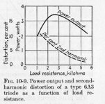
Check the increase of distortion plotted on a triode where D% is plotted against load resistance.
That graph is typical of all common triodes, only the scale factors are different.
Schade FB driving back into a pentode plate does not get into that problem.
Extra parts required for this alternative circuit are simply the 6SJ7 screen resister & cap. And the Schade FB resister
It can be fixed bias by simply using a 1.5V battery on the 6SJ7 control grid if you like.
If this looks like something for a future build let me know. I'll fill it out. 👍
Looks like it helps some with the DF. A simple fix, sometimes that is all that is needed.
Connecting the input plate to the output plate of the 6N6G is the same as triode strapping any of the common power pentodes.
In the data sheets covering many power pentodes both modes of operation are often listed & the plate/grid plots shewn.
If a 6N6G were plotted with its plates tied together it would simply look like any common triode.
But there are some folks who do put forth an argument that it is a form of NFB.
I've got an old technical paper (not mine) on file here somewhere covering that,
I'm not sure why the 26, 27 & 30 are so popular in these amps of the present era. I see no advantages & plenty of problems.
But the 30 makes a great regen detector, even when running at 22.5V of B+. With some olde headphones & 100 feet
of outdoor antenna. With a lightning arrestor too!
So this AM I've put a simple alternative together that will make your 6N6G sing like it was meant to do.
The front end is a 6SJ7 sharp cutoff pentode. That gets some gain so that Schade NFB can be used.
The rest of the amp remains the same. The 6SJ7 could just as well be a 6J7, 6C6, 77 or 57 with a slight reduction in the final DF.
The resulting amp has about 14.35 db Schade NFB & DF is greater than 3. Full 4W is possible with just 2.5V RMS at the front end.
The sim in this case is still in the form I would have used as a first pass to check if the design was worth going forward with.
The gain of each part is shewn in one Sim along the bottom & based on the no FB condition switch 'A' open.
The other Sim shews the condition while Schade NFB is connected.
Some people are allergic to using pentodes here on DIY. But look at the comparative results from RDH4 running
a 6J7 in pentode vs triode modes. Up to a certain level the pentode mode is better in terms of distortion.
NFB back to the plate of a triode is not the best idea either. The Schade FB resister looks like its value divided by
gain of the 6N6G power stage plus one. So the 220K FB resister looks like 220 / 11.86 or 18.55K.
If the 27 (or 26) had a plate resistor of say 27K that would now be in parallel with that 18.55K. And the 100K following grid resister.
The bottom line is a plate load of 9.91K, a long way from what the original design intended.
Check the increase of distortion plotted on a triode where D% is plotted against load resistance.
That graph is typical of all common triodes, only the scale factors are different.
Schade FB driving back into a pentode plate does not get into that problem.
Extra parts required for this alternative circuit are simply the 6SJ7 screen resister & cap. And the Schade FB resister
It can be fixed bias by simply using a 1.5V battery on the 6SJ7 control grid if you like.
If this looks like something for a future build let me know. I'll fill it out. 👍
Attachments

John, I'm still not grasping how connecting the plates of the 6N6G is anything like triode strapping a pentode.Connecting the input plate to the output plate of the 6N6G is the same as triode strapping any of the common power pentodes.
In the data sheets covering many power pentodes both modes of operation are often listed & the plate/grid plots shewn.
If a 6N6G were plotted with its plates tied together it would simply look like any common triode.
With a pentode, I can see how the connection between the plate and screen (G2) functions as a triode since it eliminates the screen as a separate element. The screen and the plate then function as a single element but there is still a separate grid (G1) and cathode, just as there is in a true triode.
The 6N6G contains two dissimilar triodes, neither section is a pentode. The input section is a triode that's configured as a cathode follower - its cathode is connected to the grid of the output section triode.
I don't see how such a connection emulates the function of the screen in a pentode. So I don't understand how connecting the output section plate of the 6N6G to the plate of the input tube creates a triode.
The source signal still goes to the input section's grid and its cathode is still connected to the output section's grid. I don't see how any of the elements of either section change or function any differently. The only difference I see is the source of the input section's plate voltage.
In one case it comes directly from the power supply (B+) and in the other it goes through the OT primary, just like the output section plate supply.
I think the interest in tubes like the 26 and 30 is that they're directly heated and many people, including myself, find that they like the sound of directly heated tubes. The difference in sound between DHTs and IDHTs that are otherwise similar, like the 26 and 27, is not something that is likely to be evident in sims or calculations.I'm not sure why the 26, 27 & 30 are so popular in these amps of the present era. I see no advantages & plenty of problems.
The main limitation that their fans usually mention is simply that their amplification factors are so low. And since the most popular DHT output tubes - like the 45, 2A3 and 300B - require more drive, they're forced to use more complicated 3 stage designs.
The whole "iSET" approach is an attempt to solve that issue by using output tubes that are significantly easier to drive, which allow the use of a single, common, low mu, DHT as an input tube. The iSET topolgogy also supports the notion that the input tube may play a larger role in the overall sound of an amp than the output tube.
In building the Nuance, I wanted to explore this alternative, iSET, approach.
Perhaps Jeff will try using the 6SJ7 with either Schade or cathode FB with his project, since he's still got it breadboarded and he's still experimenting with different input tubes. Mine is already built so I won't be changing tube sockets and trying different tubes at this point. Doing so would also require me to install a totally different filament supply.In last nights Sim I wanted to shew how the 6N6G you are using would do with OPT secondary to power tube cathode NFB.
Looks like it helps some with the DF. A simple fix, sometimes that is all that is needed.
So this AM I've put a simple alternative together that will make your 6N6G sing like it was meant to do.
The front end is a 6SJ7 sharp cutoff pentode. That gets some gain so that Schade NFB can be used.
The rest of the amp remains the same. The 6SJ7 could just as well be a 6J7, 6C6, 77 or 57 with a slight reduction in the final DF.
The resulting amp has about 14.35 db Schade NFB & DF is greater than 3. Full 4W is possible with just 2.5V RMS at the front end.
The sim in this case is still in the form I would have used as a first pass to check if the design was worth going forward with.
The gain of each part is shewn in one Sim along the bottom & based on the no FB condition switch 'A' open.
The other Sim shews the condition while Schade NFB is connected. . . .
Extra parts required for this alternative circuit are simply the 6SJ7 screen resister & cap. And the Schade FB resister
It can be fixed bias by simply using a 1.5V battery on the 6SJ7 control grid if you like.
If this looks like something for a future build let me know. I'll fill it out. 👍
Sorry for all the multiple posts but when I tried to quote sections of your earlier post to comment on the formatting was a total mess and not all of my responses were visible.
My upcoming breadboard experiments / possible builds all involve the use of directly heated pentodes for the outputs and I plan on keeping them in pentode mode so I'll likely need to employ some type of NFB scheme.Some people are allergic to using pentodes here on DIY. But look at the comparative results from RDH4 running
a 6J7 in pentode vs triode modes. Up to a certain level the pentode mode is better in terms of distortion.
NFB back to the plate of a triode is not the best idea either. . . . Schade FB driving back into a pentode plate does not get into that problem.
It can be fixed bias by simply using a 1.5V battery on the 6SJ7 control grid if you like.
If this looks like something for a future build let me know. I'll fill it out. 👍
I'm still planning on using only two stages per channel and using battery grid bias on the input tubes and I'll likely stick with directly heated input tubes. I realize that the 26, 30, and similar low mu triodes won't work. I've got some others in mind, some triodes and some pentodes.
I'll likely start a new thread once the breadboarding process is underway. As always, your perspective and suggestions are welcome and appreciated.
John, I'm still not grasping how connecting the plates of the 6N6G is anything like triode strapping a pentode.
------------------------------
While interning at the research lab I built myself a simple tube curve tracer. It used one of the several TEK 530 or 540 Scopes in the lab for a display.
With the scope camera it was possible to easily record the plate characteristics of common triodes. Even did some tubes connected in Cascode.
The camera had a couple of backs, one for the Polaroid ASA 10000 we used for fast single shot traces & so on.
Another back used ordinary B&W film, there was a dark room where we could develop those.
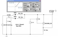
So here it is running on a simulator. The example I used is straight out of the RCA HB, a 76 direct driving a 6AC5G.
With the plates of the tubes tied together the curve at zero bias is clearly that of a triode.
This form of curve tracer uses an unfiltered waveform from a FW rectifier to provide the sweeping voltage to the plate.
Just like TEK did it, their sales person of the day advised me of that. A very knowledgeable guy, I expect he is long gone.
------------------------------
While interning at the research lab I built myself a simple tube curve tracer. It used one of the several TEK 530 or 540 Scopes in the lab for a display.
With the scope camera it was possible to easily record the plate characteristics of common triodes. Even did some tubes connected in Cascode.
The camera had a couple of backs, one for the Polaroid ASA 10000 we used for fast single shot traces & so on.
Another back used ordinary B&W film, there was a dark room where we could develop those.
So here it is running on a simulator. The example I used is straight out of the RCA HB, a 76 direct driving a 6AC5G.
With the plates of the tubes tied together the curve at zero bias is clearly that of a triode.
This form of curve tracer uses an unfiltered waveform from a FW rectifier to provide the sweeping voltage to the plate.
Just like TEK did it, their sales person of the day advised me of that. A very knowledgeable guy, I expect he is long gone.
Attachments
Well, I know zilch about sims and curve tracing but I'm not surprised that if you do a curve trace on a triode that the curve looks like a triode.So here it is running on a simulator. The example I used is straight out of the RCA HB, a 76 direct driving a 6AC5G.
With the plates of the tubes tied together the curve at zero bias is clearly that of a triode.
This form of curve tracer uses an unfiltered waveform from a FW rectifier to provide the sweeping voltage to the plate.
Since both sections are triodes, I would expect that the curve looks like a triode whether the input section's plate is supplied directly from the B+ or from the plate of the output section. Perhaps the difference would be that, if the input plate is supplied from the B+, you would have two separate curves instead of one combined curve. Maybe the plate to plate connections allows you to trace a single curve. I can see where that might be helpful.
Certainly, if you triode strap a pentode you would expect the resulting curve to look like a triode, not a pentode. But if you start with a triode, I suspect you would not end up with a curve that looks like a pentode in one case, and a triode in another case, simply because the plate is supplied from a different source.
I do prefer the sound with the plates tied together. But, as I mentioned, I installed a switch that allows the input plate to be supplied by the B+ in case I'm using very inefficient speakers that need more power and I want to listen at higher volume than I normally do.
The example I used is straight out of the RCA HB, a 76 direct driving a 6AC5G.
As a bit of an aside:
I'm aware that the combination of the 76 and 6AC5G is supposed to be similar to the 6N6G. At the very least, the 6N6G offers the advantage of being simpler (one tube, one socket) but the data sheets also indicate that the 6N6G produces a bit more power at 5% distortion than the combo does at 10% or more. Who knows if the difference is audible under normal listening conditions.
A closer look at the original data sheets indicates that the sections of the 6N6G are not exactly the same as the 76 and the 6AC5G. I didn't realize it before but the 6B5 (the electrically equivalent, 6 pin, predecessor of the 6N6G) and the 6AC5G were both developed by Triad.
The 6B5 was the earlier development with its data sheet dated 1/29/35 while the data sheet for the 6AC5G is dated 9/29/37.
The data sheet for the 6AC5G states: "The Triadyne 6AC5G is a positive grid Class A Power Amplifier Triode which is similar to the output section of the well known type 6B5, and requires a type 76 driver tube to be connected with it in the usual "Dynamic Coupling" type of circuit. The type 76 tube performs the same function as the input section of the 6B5 Triadyne. While the positive grid characteristic of the 6AC5G suggests typical Class B service, the tube has been designed to give optimum performance in Class A service with the 76 driver. In particular, the plate and grid current and grid voltage of the 6AC5G have been designed to match the type 76 tube."
While the simplicity of a single tube and socket might appeal to DIY builders today, ironically, the 6AC5G was developed precisely because it was more complicated. The reason for developing this two tube combination was because radio manufacturers were touting the number of tubes in their advertising, with more tubes being synonymous with higher quality and, obviously, higher sales price and higher profit. And, even more ironically, Triad developed this combo to compete with their earlier development, the 6B5, even though the combo apparently didn't perform as well.
"Triad has designed the 6AC5G for set manufacturers to use in AC models nominally employing the type 41 power tube. The 6AC5G offers a low cost method of increasing the number of tubes in the set while definitely improving the quality and performance." . . . "As mentioned previously, the 6AC5G characteristics have been designed to match a type 76 driver tube. Other similar types of triode tubes will not operate efficiently as drivers because of the differences in amplification factor and plate current."
https://tubedata.edebris.com/sheets/201/6/6AC5G.pdf
The reason for developing this two tube combination was because radio manufacturers were touting the number of tubes in their advertising,
-------------------------
For sure that was a common dodge. How about two 6SQ7's, one for the diodes in the detector, the other to do the gain! 😱
-------------------------
For sure that was a common dodge. How about two 6SQ7's, one for the diodes in the detector, the other to do the gain! 😱
I know nothing about radios or whatever alternatives existed.The reason for developing this two tube combination was because radio manufacturers were touting the number of tubes in their advertising,
-------------------------
For sure that was a common dodge. How about two 6SQ7's, one for the diodes in the detector, the other to do the gain! 😱
Triad, as a company, was obviously trying to sell more tubes to a wider market, which is exactly what any company would want to do. They were simply trying to adapt to the demands of a changing marketplace by developing new products. And, of course, this was during the Great Depression, to boot.
From what I understand, they were the only privately owned tube manufacturer at that point so they were up against some stiff competition. Regardless of how it ultimately turned out, I give them credit for being innovative.
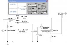
For Charlie, rdrouin & the lurkers if there are any still watching, here is how the odd looking schematic I used translates
into an ordinary version. Just three connexions where we would expect them put the 6N6G where it should be.
And a B+ PS added into the 6N6G plate circuit.
This one allows calculation of DF improvement when NFB from the OPT is fed back into the cathode of the power tube.
This technique is fairly common & often used with or without other FB. In the McIntosh 1/2 the primary signal goes
back the the cathodes.
The switches A & C are those keys on the KB used to calculate the degree of FB & the DF.
Attachments
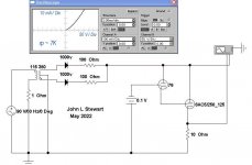
Thru the magic of Modern Electronics & Dead Reckoning, here are the estimates of the
plate resistance of the 76/6AC5G combo, just as they are listed for most other toobZ.
Sweeping the plate is again by a rectified but unsmoothed sine wave.
The AC voltages applied are nothing to do with the regular PS, but rather provide the sweep.
No smoke at all.
So as a triode the rp looks like ~7K while the pentode connexion looks like ~55K.
Very muck like any common power pentode. Which it is intended to replace in an
operating circuit.
Attachments
I first became interested in this line of tubes (6N6G, Etc) about 20 yrs ago. It looked like a way to simulate pentodes in the Electronic Workbench simulator.
EWB was developed as a teaching tool right here in "The Big Smoke', Toronto. But by that time vacuum tubes were no longer important.
There is a triode model in EWB that can easily be manipulated, but no vacuum pentodes or diodes.
The 6N6G & the other evidence of the plate curves of the 46 & 49 looked like a way out for pentodes, Two triodes would work.
The driver triode needed a mu of say 10 while the power triode with a mu of about 50 looked promising.
So in 2003 a 6SN7 & 6F6 were hooked up on the bench & measurements made, Refer to the attachment outlining that work.
EWB was sold to NI. The people & knowledge moved to Texas.
Today's simulation shew the 6SN7 & 6F6 combination to have plate resistance similar to what I measured in 2003.
I've used this trick often to stuff pentodes into a simulation, the results are what I was looking for.
Another interesting point is that some of the 6N6G data sheets shew the high mu section of the tube to be a tetrode
with G1 & G2 joined, just as in the experimental work.
I wonder if there is still an audience out there! 😀
Attachments

Interesting stuff, as always, but most of it is over my head.I wonder if there is still an audience out there! 😀
I'm still wondering (posts #64 & #69) how powering the input section from a different voltage source (the output section plate vs B+) is the same as triode strapping a pentode. Are you saying that a cathode follower and the screen of a pentode are functionally the same?
I'm hoping Jeff will eventually give us an update on his project. Perhaps he has tried some of the input tubes you suggested in place of the 27 and/or tried using cathode feedback.
- Home
- Amplifiers
- Tubes / Valves
- Developing a 6N6G Integrated Amplifier