Nothing groundbreaking here. I've started developing a 2A3 SET amp by trying different published circuits, and will use this thread to record information for those who come after and foster discussion for those currently interested. At the moment, I'm trying different topologies from well-known circuits to gain a sense of what the general behavior and sound characteristics are like. Once I discover a favorite, I'll either just do a final build or tweak it to taste.
The order of progression will be as follows. For now I'm sticking to cap- and direct-coupled designs because I don't want the expense of an interstage transformer. I might add more circuits to this if I feel like it.
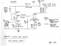
1. Joseph Esmilla's simple 45/2A3 circuit, which uses 1/2 6SL7 per channel as a simple voltage amp. I was surprised by how enjoyable this circuit is to listen to. Gorgeous and highly developed timbre on acoustic instruments, fast, dynamic, very detailed, and very musical. Jazz guitar and small ensemble classical like Ravel and Stravinski were excellent.
2. Joseph Esmilla's SRPP 6SL7 - 2A3. I ran the output stage at 250Vak/60mA and made sure to elevate the 6SL7 heater voltage with the power supply divider and 6.3V winding center tap as in Joseph's schematic, so as not to exceed the heater-cathode limit in the 6SL7 datasheet (the upper triode cathode is at nearly 150V). This circuit was "better" than the simple version in the technical sense that it provided even more detail and noticeably greater bass extension (not that it was lacking in the simple version). It's perhaps a little more neutral and polite than the simple 2A3, but still develops all the layered timbre and dynamism. I could live with either circuit and was very happy with both, maybe with a slight preference for the simple. If I swing back in this direction I'll try both again.
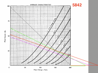
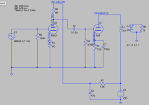
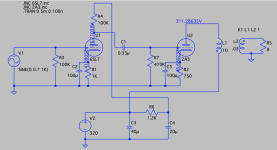
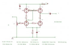
3. Self-designed 5842 voltage amp into a 2A3. Given that the 6SL7 runs at very low current in the above schematics (about 0.6mA), wanted to hear what would happen in an arrangement with more current driving the 2A3. So, I picked 5842 and attempted to run it at its published op point of 150Vak/25mA, using a 60R cathode resistor and a 6K plate load resistor with a supply voltage of 300V. In the load lines I layed out, this one (red line in the attached screenshot) seemed the most linear. When I first switched on the breadboard, using the same rectifier (5R4GY) and power supply as in # 1 & 2, the voltage was expectedly lower than before (5842 at 125Vak). So I swapped in a 5U4GB and now the 5842 is at 130V/24mA (the light purple line in the attached screenshot). This arrangement is not bad but sounds a bit lackluster, without quite the timbre, detail, and dynamism of the 6SL7 circuits and a less perceptible soundstage. It's also a little grainy. I might switch in a GZ34 to see if the 5842 gets up to 150Vak and sounds different. Then I'll try lowering the 5842 current to 10mA or so to see if the sound gets more dynamic. But at this point I'm more inclined to move on to the 6C6 circuit, which appears to be an answer to the WE91A.
One thing I need to do is learn how to calculate the amount of current needed to drive the following stage without slewing problems. I think Gordon Rankin demonstrates that in his Bugle 45 article in Sound Practices.
The order of progression will be as follows. For now I'm sticking to cap- and direct-coupled designs because I don't want the expense of an interstage transformer. I might add more circuits to this if I feel like it.
- JE Labs simple 2A3
- JE Labs SRPP 6SL7- 2A3
- 5842 - 2A3
- Radiotron 6C6 - 2A3
- Lipman direct-coupled 6SF5 - 2A3
1. Joseph Esmilla's simple 45/2A3 circuit, which uses 1/2 6SL7 per channel as a simple voltage amp. I was surprised by how enjoyable this circuit is to listen to. Gorgeous and highly developed timbre on acoustic instruments, fast, dynamic, very detailed, and very musical. Jazz guitar and small ensemble classical like Ravel and Stravinski were excellent.
2. Joseph Esmilla's SRPP 6SL7 - 2A3. I ran the output stage at 250Vak/60mA and made sure to elevate the 6SL7 heater voltage with the power supply divider and 6.3V winding center tap as in Joseph's schematic, so as not to exceed the heater-cathode limit in the 6SL7 datasheet (the upper triode cathode is at nearly 150V). This circuit was "better" than the simple version in the technical sense that it provided even more detail and noticeably greater bass extension (not that it was lacking in the simple version). It's perhaps a little more neutral and polite than the simple 2A3, but still develops all the layered timbre and dynamism. I could live with either circuit and was very happy with both, maybe with a slight preference for the simple. If I swing back in this direction I'll try both again.
3. Self-designed 5842 voltage amp into a 2A3. Given that the 6SL7 runs at very low current in the above schematics (about 0.6mA), wanted to hear what would happen in an arrangement with more current driving the 2A3. So, I picked 5842 and attempted to run it at its published op point of 150Vak/25mA, using a 60R cathode resistor and a 6K plate load resistor with a supply voltage of 300V. In the load lines I layed out, this one (red line in the attached screenshot) seemed the most linear. When I first switched on the breadboard, using the same rectifier (5R4GY) and power supply as in # 1 & 2, the voltage was expectedly lower than before (5842 at 125Vak). So I swapped in a 5U4GB and now the 5842 is at 130V/24mA (the light purple line in the attached screenshot). This arrangement is not bad but sounds a bit lackluster, without quite the timbre, detail, and dynamism of the 6SL7 circuits and a less perceptible soundstage. It's also a little grainy. I might switch in a GZ34 to see if the 5842 gets up to 150Vak and sounds different. Then I'll try lowering the 5842 current to 10mA or so to see if the sound gets more dynamic. But at this point I'm more inclined to move on to the 6C6 circuit, which appears to be an answer to the WE91A.
One thing I need to do is learn how to calculate the amount of current needed to drive the following stage without slewing problems. I think Gordon Rankin demonstrates that in his Bugle 45 article in Sound Practices.
Attachments
Last edited:

What output transformer (OPT) did you use?
The same OPT for all 3 amplifiers?
Primary impedance?
Single Ended, Air Gapped . . . I hope so.
Maximum primary DC current rating?
Secondary Tap impedance?
Loudspeaker model, and its Nominal Rated Impedance?
What is the DCR of your loudspeaker? (that is almost certainly the minimum impedance in the bass and lower midrange frequency range).
Can your power supply transformer supply 60mA, and 25mA = 85mA?
Do you have a bleeder resistor across the B+? Need to add that current too. Another 5mA to 10mA.
Safety First! Prevent the "Surviving Spouse Syndrome". Use a Bleeder Resistor.
Are you using a hum balance potentiometer if you are using AC on the 2A3 filaments?
DC on 2A3 filaments?
Sounds like you are having fun already.
Happy designing, happy building, and happy listening!
For those following along, using a GZ34 gave another 10 volts across the 5842, for 140Vak/25mA, and of course a few more volts across the 2A3s. It sounded a little snapper but not as good as the 6SL7.
OPTs are O-Netics Level 1 specifically designed for 2A3 - SE, air-gapped, spec'd to run classical 2A3 operating points, so minimum 60mA primary current capacity but probably more. 3.5K into 4, 8, 16. The final build will have speaker binding posts for 8 and 16, with an internal L-Pad on the 4 for headphones. DCR, inducatance and all that is in the attached sheet from Bud Purvine. These might actually be the best OPTs I've owned, probably even better then Electra-Print low-IMD models, and those are excellent.
Speakers are self-made trapezoidal Onken with 15R Lowther PM6A, unfiltered, in a small home office.
PT is a Weber WPT30, 560Vct/600Vct @ 250mA, 5V @ 3A, 6.3V @ 7A. I'm using the 560V windings at present.
2A3s are AC heated with 2.5V 6A Triad transformers. Cathode resistor and bypass capacitor are on the center tap wire. No hum pot needed; they're actually very quiet. I might add one for the final build since there will be a headphone jack.
Input tubes are AC heated too.
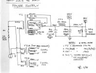
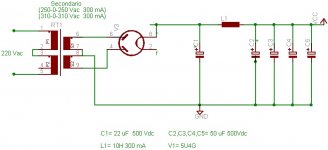
Power supply is a choke pi filter, plus an additional RC filter for dropping voltage to the input tube -- I think 15u, 10H/155R, 100u (B+), split here for 1.2K & 47uF in each channel. Just using parts I had lying around that could meet the voltage requirements. I'll do up a proper power supply once I figure out the signal circuit.
All this is just for playing around on the breadboard for now. The full dress PS design, layout primping, wire twisting, shielding yadda yadda yadda will all be handled once the final circuit is set. Its requirements will dictate chassis design, which will be an internally shielded, exotic hardwood, exquisitely finished, wipe-the-drool-off-your-shirt, family heirloom quality type of affair.
OPTs are O-Netics Level 1 specifically designed for 2A3 - SE, air-gapped, spec'd to run classical 2A3 operating points, so minimum 60mA primary current capacity but probably more. 3.5K into 4, 8, 16. The final build will have speaker binding posts for 8 and 16, with an internal L-Pad on the 4 for headphones. DCR, inducatance and all that is in the attached sheet from Bud Purvine. These might actually be the best OPTs I've owned, probably even better then Electra-Print low-IMD models, and those are excellent.
Speakers are self-made trapezoidal Onken with 15R Lowther PM6A, unfiltered, in a small home office.
PT is a Weber WPT30, 560Vct/600Vct @ 250mA, 5V @ 3A, 6.3V @ 7A. I'm using the 560V windings at present.
2A3s are AC heated with 2.5V 6A Triad transformers. Cathode resistor and bypass capacitor are on the center tap wire. No hum pot needed; they're actually very quiet. I might add one for the final build since there will be a headphone jack.
Input tubes are AC heated too.
Power supply is a choke pi filter, plus an additional RC filter for dropping voltage to the input tube -- I think 15u, 10H/155R, 100u (B+), split here for 1.2K & 47uF in each channel. Just using parts I had lying around that could meet the voltage requirements. I'll do up a proper power supply once I figure out the signal circuit.
All this is just for playing around on the breadboard for now. The full dress PS design, layout primping, wire twisting, shielding yadda yadda yadda will all be handled once the final circuit is set. Its requirements will dictate chassis design, which will be an internally shielded, exotic hardwood, exquisitely finished, wipe-the-drool-off-your-shirt, family heirloom quality type of affair.
Attachments
I've been using 2a3 amps for 2 or 3 years now. My findings - as a musician who listens to a lot of classical and opera - have been:
I like simplicity after 14 years of building complex DHT circuits with massive power and filament supplies. So my daily amp is a pair of CV6 into 2a3 outputs, nothing more. Since I don't need more gain, and I love the rather unusual CV6 with its 2 top caps, that's good enough to keep me happy. I'm building an alternative 3-stage amp but it is taking a while because I don't really need it, however nice it sounds, and it does sound very nice from my prototype. A DHT input is the best front end I know of for any amp.
I have 2 pairs of O-Netics - Level 1 3.5K and his 2a3 Wright Sound OPT which I slightly prefer. But my daily amp uses NP Acoustics amorphous core 3.5K OPTs from Vietnam.
- CCS active loads have a slight edge to them which I can't accept in classical/opera. Same with SIC diode bias. As far as I know Thomas Mayer doesn't use solid state in his designs and I can understand that. I do, however use Rod Coleman's regs on DHTs, though I must admit that my 2a3 output stage uses AC heating mainly because it takes up less space.
- I favour resistor loads because they are pure on acoustic instruments, though I also have plate chokes which aren't presently in use. If I have to use a cathode bypass I use a DC Link cap. With a DHT I try to use filament bias whenever possible.
- My simple 2-stage solution uses twin sockets - a 9 pin for E180CC and an octal one for a 6SN7 (or 2 for 6J5 types) with the same circuit, so users have the choice of more or less gain depending on their system sensitivity. They can use either of the tubes.
- My 3-stage solution would be more like the Sun/JE Labs but with different tubes. The input tube would be a 2P29L in filament bias to get the DHT sound right at the start. The driver tube is still open to change. At present 6J5 types like CV6, but I'm trying out a couple of other octals with less gain - 6AH4 and 1626. With a 3 stage amp a DHT input tube is essential to the overall sound. What you might lose by adding a stage you gain by the high quality of that stage.
I like simplicity after 14 years of building complex DHT circuits with massive power and filament supplies. So my daily amp is a pair of CV6 into 2a3 outputs, nothing more. Since I don't need more gain, and I love the rather unusual CV6 with its 2 top caps, that's good enough to keep me happy. I'm building an alternative 3-stage amp but it is taking a while because I don't really need it, however nice it sounds, and it does sound very nice from my prototype. A DHT input is the best front end I know of for any amp.
I have 2 pairs of O-Netics - Level 1 3.5K and his 2a3 Wright Sound OPT which I slightly prefer. But my daily amp uses NP Acoustics amorphous core 3.5K OPTs from Vietnam.
Last edited:
Nice to see a revisit to simple and organic circuits - all about the tone, and I look forward to reading more as things develop.
SRPP working into 470k - I wonder what might be 'found' replacing it with 500k rheostat and making some on the fly adjustment.
No surprise that you like resistor loaded 6SL7 - reminds me of the JC circuit, if you have the B+ it could be worth a try.
Cheers
SRPP working into 470k - I wonder what might be 'found' replacing it with 500k rheostat and making some on the fly adjustment.
No surprise that you like resistor loaded 6SL7 - reminds me of the JC circuit, if you have the B+ it could be worth a try.
Cheers
Attachments
Last edited:
ISCMMS,
What is your purpose of changing the output tube g1 grid resistor from 470k to a 500k rheostat?
1. It will make the low frequency roll off earlier, with the 0.22 uF coupling cap (470k versus less than 470k).
2. It will change the load on the SRPP.
That will change the maximum voltage swing; and will change the distortion.
Also, it will change the amount of any cancellation of the second harmonic distortion of the SRPP versus the 2nd harmonic distortion of the 2A3 stage.
What else were you wanting the 500k rheostat, versus 470k to do?
Thanks!
Hi 6A3sUMMER,
Yes, distortion profile of SRPP and subsequent cancellation with that of the output stage - just a quick experiment without consideration to LF.
I believe the insight will be worthwhile - over and above the apparent LF loss/phase shift even when approaching 1/3 - 1/4 the 470k value. If the experiment yields 'improvement', increase the capacitor value and adjust the 'resistor' value lower still, until it becomes 'worse', then back it off a bit 😎
As far as 'else', there maybe benefit in having a lower impedance at output tube grid wrt 0V.
Cheers
Hi ISCMMS,
The distortion of the 2A3 stage is dependent on the load that is presented to it.
So, the 2A3 2nd harmonic distortion changes when the loudspeaker impedance changes; and loudspeaker impedance is not a constant, instead it varies all over the map versus the frequency.
Draw a few load lines on the set of 2A3 plate curves, and then use the RCA tube manual formula to calculate the 2nd harmonic distortion, versus the slope of the load lines.
That means the SRPP 2nd harmonic distortion only partially cancels the 2A3 2nd harmonic distortion, (or with luck only fully cancels at one particular loudspeaker impedance).
Single ended amplifier driver and output cancellation is a great idea, but very hard to maintain across the 20Hz to 20kHz frequency range.
Hmmm, that makes me think . . .
If you are looking for 2nd harmonic distortion that cancels as the loudspeaker impedance varies widely, then guess what . . . Push Pull does that, because the cancellation is done in the output stage; the push pull pair of tubes always see the same load impedance versus frequency, no matter how widely it varies from 20Hz to 20kHz.
Single ended 2 stage amplifiers "serial 2nd harmonic cancellation can not do that".
Last edited:
For those following along, using a GZ34 gave another 10 volts across the 5842, for 140Vak/25mA, and of course a few more volts across the 2A3s. It sounded a little snapper but not as good as the 6SL7.
OPTs are O-Netics Level 1 specifically designed for 2A3 - SE, air-gapped, spec'd to run classical 2A3 operating points, so minimum 60mA primary current capacity but probably more. 3.5K into 4, 8, 16. The final build will have speaker binding posts for 8 and 16, with an internal L-Pad on the 4 for headphones. DCR, inducatance and all that is in the attached sheet from Bud Purvine. These might actually be the best OPTs I've owned, probably even better then Electra-Print low-IMD models, and those are excellent.
Speakers are self-made trapezoidal Onken with 15R Lowther PM6A, unfiltered, in a small home office.
PT is a Weber WPT30, 560Vct/600Vct @ 250mA, 5V @ 3A, 6.3V @ 7A. I'm using the 560V windings at present.
2A3s are AC heated with 2.5V 6A Triad transformers. Cathode resistor and bypass capacitor are on the center tap wire. No hum pot needed; they're actually very quiet. I might add one for the final build since there will be a headphone jack.
Input tubes are AC heated too.
Power supply is a choke pi filter, plus an additional RC filter for dropping voltage to the input tube -- I think 15u, 10H/155R, 100u (B+), split here for 1.2K & 47uF in each channel. Just using parts I had lying around that could meet the voltage requirements. I'll do up a proper power supply once I figure out the signal circuit.
All this is just for playing around on the breadboard for now. The full dress PS design, layout primping, wire twisting, shielding yadda yadda yadda will all be handled once the final circuit is set. Its requirements will dictate chassis design, which will be an internally shielded, exotic hardwood, exquisitely finished, wipe-the-drool-off-your-shirt, family heirloom quality type of affair.
But have you done some test lab?
Do you have the possibility to use a good sound card with ARTA or REW software?
This to understand if the Freq.answer, THD, etc are reasonable good.
A potential complication appears. The transform function giving rise to the waveform distortion associated with 2nd harmonic distortion is independent of input/output units. The cancellation that often occurs between series connected amplifier stages (volts/volts) can also manifest itself between series connected amplifiers and loudspeakers (volts/dB). REW measurements I took of an SE amp driving a PSB at three amplitude levels show consistent and significant reductions in loudspeaker 2nd HD across wide frequency ranges with the appropriate speaker absolute phase at the output binding posts.Push Pull does that, because the cancellation is done in the output stage
This needs more investigation and comparison to a 'blameless' low HD amplifier to tighten up the hypothesis but the results described were consistent as long as the amplifier and loudspeaker contributions to acoustic 2nd HD were comparable.
Things get complicated all by themselves.
rdf,
Thanks!
Yes, the matter is complicated.
Here is one of several complications:
An experiment used a 2A3 single ended amplifier that had a moderate amount of 2nd harmonic distortion.
A 100 Hz sine wave from a very low distortion oscillator was applied to the 2A3 amplifier input.
A double pole, double throw switch was wired from the amplifier output to a Spica TC-50 speaker to allow phase reversal of the signal to the speaker.
Of course the TC-50 has its own 2nd harmonic distortion.
When the switch was flipped from one connection, to the opposite phase connection, guess what . . .
The Timbre of the 100 Hz sine wave changed (addition versus partial cancellation of the 2nd harmonic distortion).
Have fun, all of you that want to try this.
Just listen for the difference in the Timbre.
OK, I've now breadboarded the Radiotron 6C6 --> 2A3 as originally published and really like it. So much more effortless and musical than the 5842. Not surprisingly, it sounds a bit like the WE91A. Initial impression is that it is very detailed and dynamic, with beautiful tonal development. Lots of drive and sustain. Jazz guitar sounds very fast. One thing I'd like to mention is that the 6C6 has a metal film cathode resistor and tantalum bypass cap. I've got a nicer 2K resistor and a Sprague electrolytic that I'll swap in later just to see if it affects the sound. I'm going to listen to this for about a week.
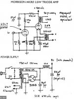
In terms of preference, it's close to the 6SL7 circuits described above (to which I'll add the JC Morrison one -- thanks ISCMMS; I have PTs that can achieve those voltages no problem).
With 5R4GY driving the power supply, the voltages are pretty spot on for the original circuit:

The input stage provides so much gain that a line preamp would be completely unnecessary with this circuit. When I modeled it in LTSpice, the input sensitivity was 0.25V, and that feels about right here.
Andy: Curious re: DHT in front. In your experience, does it matter whether that DHT is in the amplifier or in a previous stage, such as a line preamp? I'm also working on a line preamp that will use type 26 but wondering if it might be worth placing it in an integrated amp.
ISCMMS, 6A3sUMMER, rdf, waltube: thanks for the input and discussion of distortion. I suspect I'm less allergic to it, especially 2nd order harmonic, than some might be.
waltube: I've got an oscilloscope and signal generator, but no test equipment beyond that. I don't have a distortion analyzer, for instance. I'm mainly just designing for sound here.
In terms of preference, it's close to the 6SL7 circuits described above (to which I'll add the JC Morrison one -- thanks ISCMMS; I have PTs that can achieve those voltages no problem).
With 5R4GY driving the power supply, the voltages are pretty spot on for the original circuit:
The input stage provides so much gain that a line preamp would be completely unnecessary with this circuit. When I modeled it in LTSpice, the input sensitivity was 0.25V, and that feels about right here.
A DHT input is the best front end I know of for any amp.
I have 2 pairs of O-Netics - Level 1 3.5K and his 2a3 Wright Sound OPT which I slightly prefer. But my daily amp uses NP Acoustics amorphous core 3.5K OPTs from Vietnam.
Andy: Curious re: DHT in front. In your experience, does it matter whether that DHT is in the amplifier or in a previous stage, such as a line preamp? I'm also working on a line preamp that will use type 26 but wondering if it might be worth placing it in an integrated amp.
ISCMMS, 6A3sUMMER, rdf, waltube: thanks for the input and discussion of distortion. I suspect I'm less allergic to it, especially 2nd order harmonic, than some might be.
waltube: I've got an oscilloscope and signal generator, but no test equipment beyond that. I don't have a distortion analyzer, for instance. I'm mainly just designing for sound here.
Hey 6A3, how about some examples of circuits you have designed & built.Have fun, all of you that want to try this.
Just listen for the difference in the Timbre.
I've only ever come upon one & that several years back. THX 🙂
Hi,That means the SRPP 2nd harmonic distortion only partially cancels the 2A3 2nd harmonic distortion, (or with luck only fully cancels at one particular loudspeaker impedance).
I'm not sure if the highest degree of cancellation will 'sound best' but suspect there will be an 'ideal' value of load impedance to the SRPP, which may or may not be the same thing. Super cool to know that although there are many variables and considerations, all you have to do is turn the pot and listen, what a great hobby 🙂
Cheers
How so? A quick cakc shews that configuration freq response to be down 3 db at 6,4 KHz,Initial impression is that it is very detailed and dynamic, with beautiful tonal development
OK for when the 6C6G was in common use. with AM radio & 78 RPM disc.🙂
How so? A quick cakc shews that configuration freq response to be down 3 db at 6,4 KHz,
OK for when the 6C6G was in common use. with AM radio & 78 RPM disc.🙂
How did you do that quick calc?
Approximations (That Work)
Get out your copy of the RCA tube manual that contains the interelectrode capacities of the tubes to be used. In this case we are calculating the 3db down frequency of the interstage network between the 6C6 & the 2A3.
So for the 2A3 the grid-plate capacity is 16.5 pF. The 2A3 input capacity is 7.5 pF. And the output capacity of the 6C6G is 6.5 pF.
To account for Miller Effect of the 2A3, we need to know the 2A3 gain. For a triode power stage, gain depends on the load resistance but for this calc by eyeball I just used G = 3.5. The Miller Capacity is then 3.5 X 16.5 or 57.75 pF.
That all adds up to 71.75 pF, (57.75 + 7.5 + 6.5)pF. Making allowances for strays of wiring capacity conveniently rounds out to ~100 pF. Or 0.1(10^-9) F. All must be driven by the 6C6 load resister of 250K or 0.25( 10^6) Ohms. The Time constant RC is the product of those two numbers, 0.025 seconds. Be careful how you collect the exponents of those numbers. Otherwise crazy results follow.
Stuffing that into the formula for RC frequency 3 db down looks like ~0.16 / RC. The freq response of the circuit is already down 3 db at 6.4 KHz simply thru the interstage coupling. There are still other factors such as the response of the OPT & the input circuit. Looks like the original input Pot has been changed to 100K. That is much better. The lowest drive impedance to the following grid is now 25K when the slider is at mid resistance. But there needs to be a decoupling cap at the input of something like 0.1 microF. 🙂
Attachments
The 2A3 input capacitance including the Miller Effect capacitance is about 57.75 pF,
just as was stated by jhstewart9.
However, the triple parallel impedance that that 57.75 pF "sees" is:
The very high plate impedance, rp, of the 6C6; the 250k Ohm 6C6 plate load resistor; and the 500k 2A3 g1 resistor to ground.
That makes the -3dB point just a little higher frequency than the 6.4kHz that was stated; but it still falls much lower than 15kHz or 20kHz.
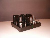
I have done a s.e. 2A3 with Gomes stage with 6N1P
In attach the proto
It is not difficult and works great with the appropriate trafo.
1 volt rms as input signal for 2,5 watt on 8 ohm.
In attach the proto
It is not difficult and works great with the appropriate trafo.
1 volt rms as input signal for 2,5 watt on 8 ohm.
Attachments

Andy: Curious re: DHT in front. In your experience, does it matter whether that DHT is in the amplifier or in a previous stage, such as a line preamp? I'm also working on a line preamp that will use type 26 but wondering if it might be worth placing it in an integrated amp.
It doesn't matter unless you want to direct couple the first 2 stages. Since a DHT tends to use up real estate it can be more convenient to use it in a separate stage, which is what I do myself. I also use outboard filament supplies with chokes to keep the field around the chokes away from the signal.
I've made 26 preamps and 4P1L preamps and several others besides but my choice would be:
- 2P29L for the easiest circuit to build in filament bias. Filament current is only 120mA. Good balanced sound, excellent mids.
- 46 for the most neutral and detailed sound that really gets you inside the music. Cathode bypass cap but you could manage filament bias with a big cathode resistor. Hungry on iron though, so I haven't attempted it.
- 10Y for a silky and dynamic sound that is likeable and involving. Filament bias isn't too difficult but sounds good with a cathode bypass also. I use DC Link caps.
I'd prefer the three above to the 26, in fact I converted a 26 preamp to 2P29L.
Once you have your DHT preamp you then only need a driver tube with a mu of around 5, so a very different circuit in the amp and in fact a very easy one. Like I said, I use 6J5 for now but will be trying 6AH4 and 1626 also. In fact you could stick a 2P29L in as driver. I've tried that and it sounds wonderful. Or even move your 26 stage into the amp as a front end.
- Home
- Amplifiers
- Tubes / Valves
- Developing a 2A3 SET