I have acquired a complete set of drivers that were used for Cerwin Vega's AT-15 speakers and would like to use them for my first DIY project. I realize the drivers may not be ideal, but at least working with them will let me start to understand the basics.
I have collected the TS parameters for all of the drivers with a DATS V3. However, in order to start modeling the enclosure, I need the Xmax for the woofer. The current version of CV does not have that information and I have not been able to find it anywhere on the Internet.
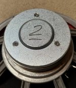
The attached image gives a rear view of the woofer. Can Xmax be determined if the pole piece is removed? I have four of the woofers, so I am good with sacrificing one of them in order to get the measurement.
Thank you for your comments and suggestions.
I have collected the TS parameters for all of the drivers with a DATS V3. However, in order to start modeling the enclosure, I need the Xmax for the woofer. The current version of CV does not have that information and I have not been able to find it anywhere on the Internet.
The attached image gives a rear view of the woofer. Can Xmax be determined if the pole piece is removed? I have four of the woofers, so I am good with sacrificing one of them in order to get the measurement.
Thank you for your comments and suggestions.
Attachments
With difficulty. It depends on what you call Xmax, since there isn't actually any fixed definition for what it even is, let alone a single method to generate a figure for it. It's not a requirement for enclosure modelling, so you can go ahead without it, although you'd probably be best sticking to one of the pioneer's optimial power-handling alignments. Otherwise, if you can't get any data on the gap & coil heights, and if it's impractical to measure them (which it usually is given the confines of the unit) I'd just try to measure the deflection in one direction by pressing (carefully) on the cone until it reaches its limit, & divide that figure by 1.41 just so you have a figure that vaguely means something. Not a lot, but none of the other calculations do either. 😉
Last edited:

Removing the pole piece can be a gamble unless you are reconing. Keeping the voice coil gap consistent can be a problem.
Happen to have an inductance meter? A rough test would be to measure inductance and push the cone in and out slightly and see where the inductance starts to drop.
Another would be to play a constant midrange tone and gently push the cone inward and outward and see where you hear a difference.
Happen to have an inductance meter? A rough test would be to measure inductance and push the cone in and out slightly and see where the inductance starts to drop.
Another would be to play a constant midrange tone and gently push the cone inward and outward and see where you hear a difference.
Hello @daqvin_carter,
Thank you for your reply.
The Dayton DATS V3 will measure inductance, but it does so with a frequency sweep. Would a purpose-built LCR meter be better for the process you mentioned?
Can Xmax be measured accurately if I am willing to sacrifice one of the woofers?
Thank you for your reply.
The Dayton DATS V3 will measure inductance, but it does so with a frequency sweep. Would a purpose-built LCR meter be better for the process you mentioned?
Can Xmax be measured accurately if I am willing to sacrifice one of the woofers?
Hello @Scottmoose,
Thank you for your reply.
Yeah, sometime in just the past day or two, I ran across some information about the problem with there not being a standardized method for deteriming Xmax.
Where does the factor if 1.41 come from? (Yes, I am a nerd and like to under the basis for things.)
Thank you for your reply.
Yeah, sometime in just the past day or two, I ran across some information about the problem with there not being a standardized method for deteriming Xmax.
Where does the factor if 1.41 come from? (Yes, I am a nerd and like to under the basis for things.)
@Wizard509 You don't actually need Xmax to design an enclosure.
Xmax is one of the characteristics determining the max SPL the system will play, but not the roll-off characteristics of the system.
I'm not sure which program you're using to simulate, but I would just guesstimate an Xmax number........for the time being.
Dave.
Xmax is one of the characteristics determining the max SPL the system will play, but not the roll-off characteristics of the system.
I'm not sure which program you're using to simulate, but I would just guesstimate an Xmax number........for the time being.
Dave.
It's the point at which you'd need to double the input voltage to reach the mechanical excursion limit. When in doubt, play it safe, as they say. Although since these are CW woofers, it would probably take a bit to kill them.Hello @Scottmoose,
Thank you for your reply.
Yeah, sometime in just the past day or two, I ran across some information about the problem with there not being a standardized method for deteriming Xmax.
Where does the factor if 1.41 come from? (Yes, I am a nerd and like to under the basis for things.)
Not sure I would sacrifice a woofer unless it is bad. Might just want to get a test signal and guess.
Also what numbers do you get from DATS? Just curious about the drivers.
The general formula is Xmax = (Voice Coil Length - Height of the Magnetic Gap) / 2. xmax would be the amount of coil poking past the gap assuming the coil is centered front to back.
If you remove the spider you can go by the amount of voice coil past the gap. You expect a drop in BL once one side of the coil drops below the gap.
Some specify xmax as the distance of travel where BL drops by 30%. Also some may exaggerate this figure.
Another place xmax gets tricky is if you have a really long voice coil and gap. Say a 30 mm magnet gap height and a 34 MM high voice coil. Xmax by the equation would only be 2MM but the excursion to reach somewhat lower BL would take a bit.
I'm not our co-member, but pretty much all lumped-element modellers are alike, with variations tending to be only in the default settings for leakage losses, vent losses, damping coefficients. If you set those as equivalents, they'll give essentially identical results for a given set of driver data, Vb, Fb. WinISD, Boxsim, Winspeakerz, Unibox, Woofer Box & Circuit Designer, Basta, BassBox Pro etc. differ relatively little in this, with the latter sometimes showing the most variations to the others simply because it uses different values as defaults for losses, damping etc., but much-of-a-muchness (as you'd expect) once adjusted as mentioned. You can use more advanced software of course like Hornresp, Akabak etc. if you feel so inclined, which moves beyond lumped-element volume modelling / pure Helmholtz assumptions.
Last edited:
Not sure I would sacrifice a woofer unless it is bad. Might just want to get a test signal and guess.
Also what numbers do you get from DATS? Just curious about the drivers.
The general formula is Xmax = (Voice Coil Length - Height of the Magnetic Gap) / 2. xmax would be the amount of coil poking past the gap assuming the coil is centered front to back.
If you remove the spider you can go by the amount of voice coil past the gap. You expect a drop in BL once one side of the coil drops below the gap.
Some specify xmax as the distance of travel where BL drops by 30%. Also some may exaggerate this figure.
Another place xmax gets tricky is if you have a really long voice coil and gap. Say a 30 mm magnet gap height and a 34 MM high voice coil. Xmax by the equation would only be 2MM but the excursion to reach somewhat lower BL would take a bit.
Attachments
Please do NOT sacrifice a working woofer for a relatively unimportant measurement.Hello @daqvin_carter,
Thank you for your reply.
The Dayton DATS V3 will measure inductance, but it does so with a frequency sweep. Would a purpose-built LCR meter be better for the process you mentioned?
Can Xmax be measured accurately if I am willing to sacrifice one of the woofers?
Unimportant here meaning:
* It will not change your cabinet design anyway, so, why bother?
Only purpose is to calm OCD anxiety, nothing more.
Why?
Because:
* Once you know it ... so what?
You can change nothing short of full reconing anyway.
If the itch is unbearable, actually measure it. 😲
Carefully cut dust cap so you can see voice coil inner face, you will be able to see copper winding through the former slit.
Measure it 😉
X max is that "extra" length + 1/2 or 1/3 gap width.
So add 0.5mm and you'll be fine.
If voice coil is translucent (most modern ones are) you can actually see copper through.
If not, such as with an aluminum former, you can still see copper through mandatory slit or former would be an undesirable shorted turn)
Can you see the cooper wire?
Excellent.
I had written a similar answer but didn't post it thinking OP wouldn't follow it anyway.
But yes, that's the "Lab quality" method.
I was about to suggest mounting a caliper above dust cap, applying DC in increments enough to rise cap 1mm each time and plotting displacement vs needed current.
Once current needed shoots upwards, you found the linear limit.
Hello @JMFahey and @markbakk,
Thank you for your replies.
It the OCD itch becomes unbearable, then I will use the method described by JMFahey. I am comfortable removing and replacing the dust cap.
@markbakk, I have several micrometers, so measuring the excursion would not be a problem, but I do not own a adjustable power supply and I don't know enough to look for one that would do what is needed. Can you suggest some options? I'll add them to my list of things to get sometime down the road.
Something like this will do the job nicely. You likely won’t need 10A nor 30V for a lot of speakers.
Xmax is not needed for sizing up a sealed box.
However, it will help determine the minimum port diameter for a vented box. If the port diameter is too small, you may get unwanted noises caused by air flow being restricted. (some programs calculate a Reynolds number to help to quantify that). Port placement in a box should provide adequate clearance between the open (internal) end of the port and any boundaries (e.g. drivers, crossover components, or inside walls). Also, the volume displaced by the vent is sometimes significant enough to account for when determining net internal volume, Vb.
The ratio of Fs/Qes is commonly used to determine if the driver is suitable for closed or vented. If the ratio is around 50, closed box usually works well. If ratio is closer to 100 then vented usually works best. Ratio of 60 to 80 may be suitable for either.
If the box will be sealed, don't worry about Xmax.
If you have a modeling program that needs Xmax, you could guess a large value, like maybe 8 mm, or 6 mm. Often, a 15" woofer has 4 or 5 mm Xmax. A 6" diameter vent is probably a typical (conservative) size for a 15". You might get by with a pair of 4" or even a pair of flared 3" ports.
Don't know about CW drivers nowadays other than some published in recent years with 14-17 mm, but at least to the mid '70s the 15"ers I was exposed to were same as Altec = 5 mm and since these appear to be similar/same 'el cheapo' speakers/woofers I auditioned right before the Covid shutdown, best to err on the side of caution (5 mm).
I would guess 4-6mm xmax by looking at the magnet. They are not subwoofers and sometimes you really do not want the inductance and moving mass that comes with 10-15mm xmax.
Subwoofers with high xmax do not usually do well above 100HZ.
They should make it up to 1Khz gracefully.
Currently listening to speakers using Electro-voice 15W drivers that would have about 3mm xmax going by coil overhang. Using only down to 80hz though. They slam well.
Subwoofers with high xmax do not usually do well above 100HZ.
They should make it up to 1Khz gracefully.
Currently listening to speakers using Electro-voice 15W drivers that would have about 3mm xmax going by coil overhang. Using only down to 80hz though. They slam well.
I would suggest a nearfield measurement with low frequency and increasing voltage, observing distorsion. Once the third harmonic h3 increases rapidly you reached xmax. I think (iirc) some manufacturers define xmax using a 10% h3 limit.
From the voltage you can derive the displacement via simulation program, such as hornresp. You could also "measure" it with a "sensing stick" that will make ugly noise once it touches the oscillating membrane (be careful!).
By the way, I tried the DC displacement method here.
Corresponding distorsion measurement here!
Last edited:
- Home
- Loudspeakers
- Multi-Way
- Determing Xmax for vintage woofer