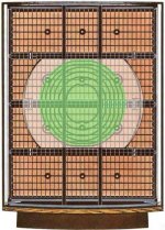
Wrong. Green area is FULL RANGE, White is FULL RANGE with some low pass, All the rest is BASS/MIDRANGE with more low pass.Just make things more clear on bass segments and panels.
Green are the delay rings only above 1 kHz.
White is mid-bass.
All the rest is bass.
This is a 4 panel model, for 6 panel models add an extra bass panel on the top and the bottom.

Never looked at it this way, but I think you got a point. The very center of the mid/high area is directly on the xformer outputs, so full range.Green area is FULL RANGE, White is FULL RANGE with some low pass, All the rest is BASS/MIDRANGE with more low pass.
Hmm.
The only 'real' lowpass I see is at the end of the transmission line; still not much of a low pass with those 300k resistors.
The transmission line delays the wave but doesn't low-pass it, does it?
Or maybe the panel segment capacitances act as progressive low passes along the transmission lines.
Jan
Attachments
Last edited:
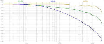
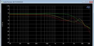
I did a quick sim on Hans Polak's model for the '63, measuring the frequency response at several places along the transmission line, so at several sections of the panel. That appears to confirm the fact that most of the panel works full range, with a drop of some 5dB at higher frequencies. The black, lower curve, is at the final bass panel drive and indeed that is low passed. Enlightening (for me at anyway).Never looked at it this way, but I think you got a point. The very center of the mid/high area is directly on the xformer outputs, so full range.
Hmm.
The only 'real' lowpass I see is at the end of the transmission line; still not much of a low pass with those 300k resistors.
The transmission line delays the wave but doesn't low-pass it, does it?
Or maybe the panel segment capacitances act as progressive low passes along the transmission lines.
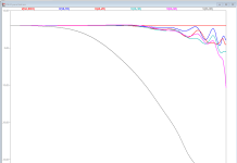
Edit: x-axis is 20Hz to 20kHz.
Jan
Attachments
 Thread split from here - https://www.diyaudio.com/community/threads/quad-esl63-dust-protection-comparative-testing.427931
Side conversations can be a welcome part of a thread, sometimes a new thread can be even better.
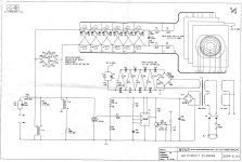
I have this ESL63 dummy load that I used for the development of my direct drive amp.
It consists of a transmission line assembly, with capacitors representing the various segment capacitances soldered between the appropriate points.
What I would like to do is compare measurements of the frequency responses at the various points on the dummy load with the results of the simulations using the Polak model as shown above.
A quick and dirty check at a few points looks like I'm on the right track (see attachment; compared with post #5), but one thing I am unsure of.
How would the actual air load on the diaphragm impact the frequency response of the transmission line assembly?
Would that change results significantly?
Jan
Attachments
The transmission line delays the wave but doesn't low-pass it, does it?
It's a damped transmission line that also acts as a low-pass filter to reduce problems due to edge effects (due to the finite size of the ESL 63). That's what the shorted windings of the coils are for. Peter Baxandall wrote about it in a chapter in a book about loudspeakers long ago.
Yes, chapter 3 IIRC in this book:
Jan
Loudspeaker and Headphone Handbook
English edition by John Borwick (Editor)Jan
No takers?How would the actual air load on the diaphragm impact the frequency response of the transmission line assembly?
Jan
I don't know how you could model it other than to test a unit in air, then put it in a vacuum chamber and test it again and compare the results. The speaker puts out sound, so it's doing work on the air, so there's definitely some resistance. The only thing you'd have to look at in the comparison is the voltage and current and their phase relationship. Maybe the air load is modeled just as a resistance, maybe it's more complex and includes some reactance if the speaker or air behavior is non linear.
Depending on room reflections that is hitting the membrane its linear and resistive.
Some dude used the ESL63 as a microphone. Im not sure how good the HF accuracy is, but in the low end it should be great..
Some dude used the ESL63 as a microphone. Im not sure how good the HF accuracy is, but in the low end it should be great..
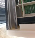
Slightly OT, concerning the mounting of the top and bottom plates on the side profiles.
All units I have seen used some sort of wood screws being forced into the quarter-open holes in the apparent hope that they cut their own thread.
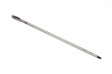
Looks wacky and seems a bit iffy and for my current build I have purchased a long (60mm) M4 machine tap. It will easily cut a nice M4 thread into the profile in one go, as deep as you want to go, and an M4 bolt fits perfectly giving a good strong connection.
Anyone here had the same or similar idea?
Jan
All units I have seen used some sort of wood screws being forced into the quarter-open holes in the apparent hope that they cut their own thread.
Looks wacky and seems a bit iffy and for my current build I have purchased a long (60mm) M4 machine tap. It will easily cut a nice M4 thread into the profile in one go, as deep as you want to go, and an M4 bolt fits perfectly giving a good strong connection.
Anyone here had the same or similar idea?
Jan
Attachments
Last edited:
The screw is not the problem. M4 or self tap doesn't make a difference at all. Maybe a little if you make the M4 very long. Countersunk 90 mm is the longest available I know of with full thread.
The plastic top and bottom and the profile itself are the problems for stability.
We solved those problems in our ESL Plus Ultimate model.
New top and bottom plate with steel, non obstructive lightweight enforcements in the profiles. Still use self tap screws though.
The plastic top and bottom and the profile itself are the problems for stability.
We solved those problems in our ESL Plus Ultimate model.
New top and bottom plate with steel, non obstructive lightweight enforcements in the profiles. Still use self tap screws though.
Last edited:
In case you missed it, there are measured frequency response and impulse responses(showing delay for each segment) posted early in the thread that were used when developing the Polak model....What I would like to do is compare measurements of the frequency responses at the various points on the dummy load with the results of the simulations using the Polak model as shown above.
A quick and dirty check at a few points looks like I'm on the right track (see attachment; compared with post #5)...
https://www.diyaudio.com/community/...ater-delay-line-inductors.338927/post-6119878
Short Answer:How would the actual air load on the diaphragm impact the frequency response of the transmission line assembly?
Would that change results significantly?
No, results will not change significantly. The electrical load impedance is dominated by the shunt electrical capacitance of the stators at all but the lowest frequencies.
At these lowest frequencies the electrical impedance is orders of magnitude higher than the source impedance, so no change will be seen in the electrical response.
Longer Answer:
Look at the complete lumped model of the ESL and its equivalent electric impedance model.
The components in the shaded box are mechanical and acoustical parameters that are reflected thru the ESL motor to the electrical domain.
They are the ESL equivalent of the familiar motional impedance in a dynamic woofer.


Two things of note:
1) The ESL motor strength, ∝ , is extremely small. The air load resistance and mass terms are divided by the motor strength squared, so the equivalent electrical impedance will be very high.
2) Whatever the motional impedance from the ESL (air + mechanical) load, it will be in parallel with the stator capacitance. This is in contrast to dynamic woofers, where the motional impedance is in series with the voice coil electrical resistance/inductance.
Since we can turn the ESL motor ON and OFF with the bias voltage, we can effectively add or remove the motional impedance at will to directly measure the effect of the air load on the electrical impedance. This ability can also be used to evaluate the magnitude of acoustic damping and diaphragm mechanical compliance(ie tension) as Baxandall outlined in Sections 3.2.7 and 3.3.8 of Chapter 3 in the book “Loudspeaker and Headphone Handbook”.
The example given by Baxandall is easily reproduced. With the no bias voltage(ie ESL motor turned off) the electrical impedance of any given ESL area is just that of the stator to stator capacitance. With the bias voltage turned on, the motional impedance that is in parallel with this stator capacitance is only visible near and below the diaphragm resonance frequency where the diaphragm motion is large and electrical impedance of the stator capacitance is relatively higher. Looking much above 100Hz, the stator to stator capacitive impedance completely swamps any motional impedance contributions in parallel with it.


If we plot the capacitive portion of these impedance curves, you can see that the motional impedance adds capacitance to the electrical impedance below resonance. In Section 3.3.8, Baxandall suggests that you can use the ratio of the measured capacitance at a low frequency (ie 5 Hz) to determine the diaphragm compliance and tension.

With modern computer measurement systems and a little more math, you can also use them to determine the acoustic resistance of any added damping mesh.
https://www.diyaudio.com/community/threads/electrostats-vs-conventional-drivers.17424/post-7013268
Steve, many thanks for a comprehensive review. This also gives me confidence that measurements on my dummy load (transmission line assembly with capacitors mimicking panel segment capacitances) are realistic.
(Just thinking out loud here). When the speaker is operating, the air has to be pushed around and 'work' is being done, especially when producing high spl. That means power has to be drawn from the system and that power reflects on the impedance (lowers it). Looking at your explanation above, the efficiency should be very high, because the work being done (air load) only has a small effect on the impedance. So, the real power delivered from an amplifier to an ESL is quite low. This is in line with my experiences with direct drive.
I need to re-read your (and Dave's) paper.
Jan
Last edited:
And if recording replayed through the same pair of ESL63, it would probably be the first true symmetrical record/replay chains ever.... I'd like to hear that. Same room, same speaker position for rec/play.Depending on room reflections that is hitting the membrane its linear and resistive.
Some dude used the ESL63 as a microphone. Im not sure how good the HF accuracy is, but in the low end it should be great..
//
- Home
- Loudspeakers
- Planars & Exotics
- Detailed operation of the QUAD ESL63