You will need a voltage amplifier (VAS); a pnp device with base connected to collector Q1, emitter connected to the positive rail, and collector connected to R15/R12. Delete R17 and replace R18 with a 6mA constant current source.
The VAS will then supply very high open loop gain, and since closed loop gain will be unity, then loop gain will equal open loop gain.
The VAS will need miller compensation, a small cap, around 47pF, across collector/base. This pulls back gain below unity at the point where phase shift reverses output over input; this guarantees stability and is essential.
Good luck. A unity gain power amp can be tricky to achieve stability since loop gain is very high. You can reduce it by putting a resistor, ie degeneration, between the emitter of the VAS and the positive rail. I'd suggest around 68R to start. You can also improve stability by using a small mosfet as the VAS; a p type, a good one to start with is the ZVP2110G, which will do Vds up to 100V.
Cheers,
Hugh
Thank you for your help.
I was thinking omitting the VAS stage to not to have excessive open loop gain.
I was thinking omitting the VAS stage to not to have excessive open loop gain.
You must have some loop gain to reduce output device distortion, and you cannot easily achieve gain from the input stage. A push pull amp without feedback is very difficult in open loop, and generally does not sound good. But a voltage amplifier is no bad thing if done right.
You can limit gain in the VAS with degeneration and a mosfet. It should not be difficult to reduce loop gain to around 35dB. That will work very well.
Hugh
You can limit gain in the VAS with degeneration and a mosfet. It should not be difficult to reduce loop gain to around 35dB. That will work very well.
Hugh
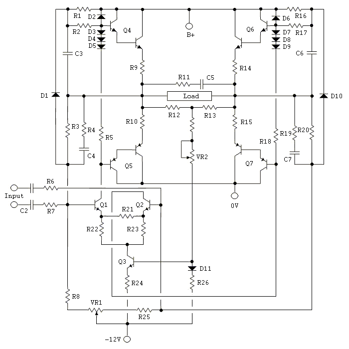
If unity gain is need, why have a VAS in the first place? Why not use some sort of local loop bias for the output stage follower? Something like HEC or some variation. The advantage would be high input Z, high damping, high current slew.😉 Since the error amplifier makes nonlinearities from the output stage transistor's nonlinear Gm and capacitance much less of a problem, it is not even necessary to place a GFB loop around it.
There are some simple EC followers out there. Here is a more elaborate follower circuit I made that works nicely and doen't require a second voltage source.🙂 This circuit could drive 50W @ 8R. In fact you could probably get 65W @ 6R. It just so happens in my circuit all the transistors are SMD except for the 2SC2690/2SA1220 and the outputs. A simpler version of this can easily be made on vero-board. Since I'm using FQP50N06 and FQP47P06 as the output transistors, the error amplifiers are put to the test as these vertical mosfets are designed for switching purposes and not intended to be used in the 'linear' region. Although not very 'linear' within that operating region, it so happens these devices are very rugged, fast, and can output very large current very quickly. With enough PS capacitance, you can weld a small screwdriver to a binding post! (did that once, blew a rail fust but not a transistor.😱😛) Though far different than BJT's, IMHO they are very good for driving reactive loads such as speakers if used properly.😀 The error amplifier transistors are mounted so that the drain pin of the output device is in physical contact for thermal feedback. J-fets don't have to be exact, just close so there is no need for a tedious selection process.
There are some simple EC followers out there. Here is a more elaborate follower circuit I made that works nicely and doen't require a second voltage source.🙂 This circuit could drive 50W @ 8R. In fact you could probably get 65W @ 6R. It just so happens in my circuit all the transistors are SMD except for the 2SC2690/2SA1220 and the outputs. A simpler version of this can easily be made on vero-board. Since I'm using FQP50N06 and FQP47P06 as the output transistors, the error amplifiers are put to the test as these vertical mosfets are designed for switching purposes and not intended to be used in the 'linear' region. Although not very 'linear' within that operating region, it so happens these devices are very rugged, fast, and can output very large current very quickly. With enough PS capacitance, you can weld a small screwdriver to a binding post! (did that once, blew a rail fust but not a transistor.😱😛) Though far different than BJT's, IMHO they are very good for driving reactive loads such as speakers if used properly.😀 The error amplifier transistors are mounted so that the drain pin of the output device is in physical contact for thermal feedback. J-fets don't have to be exact, just close so there is no need for a tedious selection process.
Attachments
Last edited:
Thank you for your contribution. The scheme you posted is too much for me to understand how it works. Anyway have you listened to it? How much feedback is there? What is the output impedance? Do you have any THD specs?
HEC output
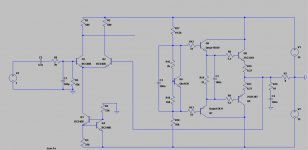
I would like to use this schematics of HEC with bipolars output. Can I directly cap couple bases of Q1 and Q2 to tube preamp, like this?
I would like to use this schematics of HEC with bipolars output. Can I directly cap couple bases of Q1 and Q2 to tube preamp, like this?
Code:
                     |----Q1
tube output----------
                     |----Q2
Attachments
Last edited:
- Status
- Not open for further replies.
- Home
- Amplifiers
- Solid State
- Designing unity gain poweramp