I have a problem with secondary side PSU.
1. How to supply a startup bias power to my PWM IC? I don't want to use 50hz small transformer.
2. Also this PSU have dual output 30V and 12V. How to compensating the feedback loop in dual output PSU? No optocoupler is needed.
PSU Spec:
Vin= 230 VAC
Vout= 30V and 17V (each 20A)
Topology: Half bridge.
Transformer: ETD49 (Pri 50. Sec1 17+17 and Sec2 7+7)
Fsw= 50Khz (Clock 100Khz)
Output L: Coupled inductor 12.5uh in EE39
Output C: 4700uF ESR:0.023
PWM IC: SG3524
Thanks.
You may wish to investigate how it is done in computer power supplies. AT style ones had a self oscillating primary side, over which the control circuit had to take control once it had some power in order to work. ATX style ones use a small auxiliary flyback converter as they have also to provide 5V standby power.
Check out Supertex and Siliconix... they have some interesting bootstrap supplies with PWM options. Supertex has cool high voltage DMOS fets that are handy as well.
😉
😉
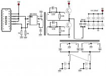
I only have this and it's a bit dirty and without component values. It contains some typo, too.
The following one also shows self oscillating:
And this is plain ATX:
An externally hosted image should be here but it was not working when we last tested it.
The following one also shows self oscillating:
An externally hosted image should be here but it was not working when we last tested it.
And this is plain ATX:
An externally hosted image should be here but it was not working when we last tested it.
For simplicity, you may also want to look at stuff you can salvage from "dead" ATX supplies. There are some very cute <20W flyback controller/switch combo chips around that are very easy to use, eg. Power Integrations' TNY263-268 & TOP22x series, ON Semi's NCP1014 etc.
They have everything except the kitchen sink built in - just add a trafo, snubber (diode/zener will do nicely), output diode/cap, a TL431 reference and an optocoupler for regulation.
BTW, I've come across many dead PC SMPUs whose standby part is still OK. Given the wide voltage ranges these little flybacks are designed for, you may even be able to use the trafo straight away.
Even a more discrete solution employing an UC3842 peak current control IC is not too complex. See the following two day project, which produces 8W and 5 outputs (no isolation, though):
An externally hosted image should be here but it was not working when we last tested it.
Thanks you for the help.
Eva, I cannot use the gate driver in ATX PSU.
It will be use to drive IGBT (SGW15N06)
I think it is better to build a new gate drive transformer.
The core is EPCOS B64290-L45-X830
ALnh=4300
NP = 10
NS1 = 10
NS2 = 10
Please see attached picture. Will this work?
Eva, I cannot use the gate driver in ATX PSU.
It will be use to drive IGBT (SGW15N06)
I think it is better to build a new gate drive transformer.
The core is EPCOS B64290-L45-X830
ALnh=4300
NP = 10
NS1 = 10
NS2 = 10
Please see attached picture. Will this work?
Attachments
Get a SMPS based Cell phone charger...trace the circuit around the secondary of switching trf..most have centertapped secondary get power from the ends connect 1 amp fast rec diode bridge (or 4 x BA157) leave out the center tap ..have to replace the filter capacitor..this works very well gives out 12 to 16 volts loosely regulated o/p WITH ISOLATION.
will try to post the pics of what i've done before tomorrow..
will try to post the pics of what i've done before tomorrow..
Power Supply help needed
We are having some problems locating a vendor that can help us on a small scale for our R&D project. What we need is DC voltage regulator that is capable of input voltages between 50 to 400 volts regulated to or converted to 32 volts out, 2 amps and 50 watts. Switching frequency as high as possible prefer above one meg. Can anyone help us with this or direct us to someone who can. One more thing it needs to fit inside of 1.5 inch tube.
We are having some problems locating a vendor that can help us on a small scale for our R&D project. What we need is DC voltage regulator that is capable of input voltages between 50 to 400 volts regulated to or converted to 32 volts out, 2 amps and 50 watts. Switching frequency as high as possible prefer above one meg. Can anyone help us with this or direct us to someone who can. One more thing it needs to fit inside of 1.5 inch tube.
- Status
- Not open for further replies.
- Home
- Amplifiers
- Power Supplies
- Designing secondary side power supply