I have a 4 way active setup and am curious if its possible to use the info from these crossover points on my active setup and design a passive crossover?
I wasn't very clear, I meant replace the active with the passive. I like the crossover points with the drivers just thinking of building a passive for fun.
A passive line level crossover? Only if it is first order, which is very unlikely.I wasn't very clear, I meant replace the active with the passive. I like the crossover points with the drivers just thinking of building a passive for fun.
Higher order passive line level would not be nearly as accurate as active, since the stages interact too much.
No, writing down the active crossover settings, ripping out the active crossover, adding passive crossover components using the written down crossover settings, making the crossover and hooking it up to a normal amplifier.A passive line level crossover? Only if it is first order, which is very unlikely.
Higher order passive line level would not be nearly as accurate as active, since the stages interact too much.
That will not work very well, unless the crossover is all first order, but yours is not.No, writing down the active crossover settings, ripping out the active crossover, adding passive crossover components using the written down crossover settings, making the crossover and hooking it up to a normal amplifier.
Two cascaded passive first order filters will not work the same, or as well as, an active second order filter can.
He got crossover frequency. Everything else would have to be done from scratch.
First measure each driver individually. (With protective cap before the tweeter, to be gentle)
Decide slopes, decide notch filters if needed or bsc. Apply l-pads if efficiencies need to be matched.
Its doable, but you are starting from almost zero.
First measure each driver individually. (With protective cap before the tweeter, to be gentle)
Decide slopes, decide notch filters if needed or bsc. Apply l-pads if efficiencies need to be matched.
Its doable, but you are starting from almost zero.

Easiest way to do this is to take a measurement of each driver with / without its active xo in place, and an impedance plot of each driver .I have a 4 way active setup and am curious if its possible to use the info from these crossover points on my active setup and design a passive crossover?
Load the without xo measurements into xsim or other simulator program.
Load the with active xo measurements into same program and use as a target curve.
The problems start when you are using digital delays and / or multiple notch filters in your digital xo.
Rob.
Maybe I answered the question biased by the tools I have available to me.
What would be the process to copy an active xo's settings with electrical measurements ?
Rob.
What would be the process to copy an active xo's settings with electrical measurements ?
Rob.
So the answer is not really, you have the crossover points but nothing else, still need to do modeling. Modeling isn't a huge issue but its not a direct swap. To some points on here, I have DSP and am using LR xovers with different slopes but all LR. Would that help at all?
Member
Joined 2009
Paid Member
I can’t see the problem, it looks doable to me. It’s line level filters that are wanted, so driver interaction is not relevant. The input impedance of the power amps can be looked up, which defines the load for the filters. And the output impedance of the source driving the filters should be known too. The XO frequencies and desired slopes are known so filters can be designed in LTspice.
I have done this several times with acceptable results. But only 3-way cross, never 4.
As mentioned by posters above - you have to measure or know the filter functions of the active crossover. Then you need to know the real impedance of the drivers in the box. Something like the DATS or WT3 is useful for that.
Plug those things into a crossover filter simulator and play with component values until you can match to active filter function. It's going to take some time and work, and will likely be rather expensive.
How are the dsp´s xo/eq/gain/delay set up by? By acoustic measurements or freehand? Is it really so good that is worth using as basis? Xo frequencies are only one and the most simple aspect of multiway crossover!
Anyway, passive line level or "driver level" xo should be designed to give smooth and phase-matched acoustic response (just like dsp). This requires driver units that have sensitivity and impedance that work together and sometimes very intensive manipulations in electric domain, which are difficult or expensive to apply, like the lowpass coil for the subwoofer and several LCR filters. Then how to match gain and timing/delays...
VituixCAD v2 is definitely the best simulation program to use. Some people find it difficult to learn, myself haven't even tried that... Please spend a few days to learn some basics of it by downloading the program (freeware) and study instructions (pdf), example case, videos and the several tutorial threads here at diyaudio and eg. HTguide.com
Have fun!
Thanks! The DSP is setup by auditioning really, it is very good and I would like to keep the sound as it is. One thing I have never gotten is the "phase response", that aspect has eluded me. I have Vituix and 4 other designing software for enclosures but never designed a crossover.How are the dsp´s xo/eq/gain/delay set up by? By acoustic measurements or freehand? Is it really so good that is worth using as basis? Xo frequencies are only one and the most simple aspect of multiway crossover!
Anyway, passive line level or "driver level" xo should be designed to give smooth and phase-matched acoustic response (just like dsp). This requires driver units that have sensitivity and impedance that work together and sometimes very intensive manipulations in electric domain, which are difficult or expensive to apply, like the lowpass coil for the subwoofer and several LCR filters. Then how to match gain and timing/delays...
VituixCAD v2 is definitely the best simulation program to use. Some people find it difficult to learn, myself haven't even tried that... Please spend a few days to learn some basics of it by downloading the program (freeware) and study instructions (pdf), example case, videos and the several tutorial threads here at diyaudio and eg. HTguide.com
Have fun!
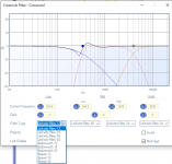
The DSP software is SigmaStudio and this is what it gives me, which helps with phase I guess. You can chose between different types of filters and I don't know if its true to the filter type or not. But there is a difference if you look at the second photo, this first one is your baseline.
If I select the LR12 filter on this one it does this dance with the signal, I'm assuming displaying the results of the improper phase alignment on the audio. You can see i changed from the LR 48 to the LR 12.
It can get pretty crazy when you start to add Bessel filters and I played with that but just settled on this setup. Some of the different settings showed a difference but there was no audible difference.
My concern is that one day if/when this DSP amp goes out that I will have to start over from scratch, also this amp has a bunch of hiss in it that I cannot figure out but sounds fine otherwise. I thought putting a conventional amp on it would be nice to test different amps with the speakers. But the crossover is the big killer here.
Attachments
Are you loading the drivers' frequency response (or impulse response) files into the Auto-EQ control? And if so, are you first flattening the drivers' responses before applying the "textbook" filters?
Aha, you can use the filter responses in post #18 instead of doing response measurements if you're looking for a way to save time.
All we have to go on presently is that you like the result and want to preserve it. That is why you've started this thread 😉 Here is one suggestion on how.. you can repeat this if you change your digital settings.
No problem, as mentioned the driver responses aren't flat like the amp software thinks they are.. so for all we know, something like that actually fixes a problem rather than creates one.it does this dance with the signal, I'm assuming displaying the results of the improper phase alignment on the audio.
All we have to go on presently is that you like the result and want to preserve it. That is why you've started this thread 😉 Here is one suggestion on how.. you can repeat this if you change your digital settings.
- Don't bother putting responses into your simulator, just use default flat responses.
- Use the amp software plots as targets in the simulator, or recreate them. (Ask if you need help.)
- In the simulator, modify the level of one of the targets to equal the difference in amplifier gain including your selected gain choices.
- Enter the impedance curves for the drivers.
- Make a speaker level crossover that meets the target curves.
Last edited:
- Home
- Loudspeakers
- Multi-Way
- Designing a passive crossover from an active setup