After reading about Merlin Blencowe's cathode coupled amp concept, I thought to give it a go.
Last week I built a nice little furball with parts I had laying around and wires running to several sockets so I could try not only ECC82 relatives, but octals and 7-pin mini's as well.
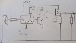
The cathode- and anode resistor are a starting point, so far from optimal for all tube types. Merely a start to get my head around the concept.
This is also my first adventure with the REW program to get an idea about the THD. I have no idea how accurate the absolute readings are, but it's good enough to compare types and settings in this experiment.
Last night I have made measurements on three Blackburn ECC82's, two RCA 5814A's, two Tesla ECC802S and an old unmarked Chinese tube I thought to be a 12AU7. After that a few UK and US 6SN7's, ECC32's, a computer tube with multiple markings (that are not equivalents according to the datasheets) and an E92CC.
Observations:
Tweaking the voltage on the grid of the second triode really works to bring THD to a minimum.
However, it's not easy to hit the absolute minimum with a regular pot. You'd need a multiturn pot for that.
Most tubes can be tweaked to similar THD levels at 1,00Vac output level: 0,03 - 0,04%. Exceptions are the Mullard that has a bit worn getter 0,08% (draws a little less current too), The NOS ECC802S's got to 0,04-0,05%, UK round-plate 6SN7 0,05%.
Pleasant surprises are the two computer types: E92CC (0,03%) and 6211/E180CC/whatever it is: 0,02%.
The Chinese tube draws a third of the current and amplifies a bit more, so this is no 12AU7. Still only 0,03% THD in this setup.
The ECC82 family has around 12V on the cathodes, or 8mA total. (except the worn Mullard).
The optimum voltage for the second grid is between 10,2 and 10,9V (leaving out the worn Mullard at 9,5V and one of the Tesla's at 11,5V).
6SN7's have between 9,7V and 10,8V (6,5-7,2mA) and 6,8-7,2V on the second grid.
Adjusting the gridvoltage/current through the second triode, changes the amplification factor.
Mind you, this is with a collection of tubes of different brands and unknown hours of use, so differences are to be expected.
It does (finally!) bring me to the question to the collective wisdom of this forum:
How to optimise this concept to make it usefull as a line amp?
Objectives:
- reduce the bias tweaking with changing/aging tubes.
- minimise THD
- minimise differences in amplification
Some options:
NFB from the output to the second grid. You could put a pot under R6 which would give both NFB and the positive voltage for the grid, but setting the pot, changes the NFB.
Replace the anode resistor with a CCS?
Replace the cathode resistor with a CCS (and feed the first triode with a resistor, turning it into an LTP)?
Insert a resistor between the cathode of the second triode and R2 and reference the grid to that? Combined with a CCS instead of R3?
Last week I built a nice little furball with parts I had laying around and wires running to several sockets so I could try not only ECC82 relatives, but octals and 7-pin mini's as well.
The cathode- and anode resistor are a starting point, so far from optimal for all tube types. Merely a start to get my head around the concept.
This is also my first adventure with the REW program to get an idea about the THD. I have no idea how accurate the absolute readings are, but it's good enough to compare types and settings in this experiment.
Last night I have made measurements on three Blackburn ECC82's, two RCA 5814A's, two Tesla ECC802S and an old unmarked Chinese tube I thought to be a 12AU7. After that a few UK and US 6SN7's, ECC32's, a computer tube with multiple markings (that are not equivalents according to the datasheets) and an E92CC.
Observations:
Tweaking the voltage on the grid of the second triode really works to bring THD to a minimum.
However, it's not easy to hit the absolute minimum with a regular pot. You'd need a multiturn pot for that.
Most tubes can be tweaked to similar THD levels at 1,00Vac output level: 0,03 - 0,04%. Exceptions are the Mullard that has a bit worn getter 0,08% (draws a little less current too), The NOS ECC802S's got to 0,04-0,05%, UK round-plate 6SN7 0,05%.
Pleasant surprises are the two computer types: E92CC (0,03%) and 6211/E180CC/whatever it is: 0,02%.
The Chinese tube draws a third of the current and amplifies a bit more, so this is no 12AU7. Still only 0,03% THD in this setup.
The ECC82 family has around 12V on the cathodes, or 8mA total. (except the worn Mullard).
The optimum voltage for the second grid is between 10,2 and 10,9V (leaving out the worn Mullard at 9,5V and one of the Tesla's at 11,5V).
6SN7's have between 9,7V and 10,8V (6,5-7,2mA) and 6,8-7,2V on the second grid.
Adjusting the gridvoltage/current through the second triode, changes the amplification factor.
Mind you, this is with a collection of tubes of different brands and unknown hours of use, so differences are to be expected.
It does (finally!) bring me to the question to the collective wisdom of this forum:
How to optimise this concept to make it usefull as a line amp?
Objectives:
- reduce the bias tweaking with changing/aging tubes.
- minimise THD
- minimise differences in amplification
Some options:
NFB from the output to the second grid. You could put a pot under R6 which would give both NFB and the positive voltage for the grid, but setting the pot, changes the NFB.
Replace the anode resistor with a CCS?
Replace the cathode resistor with a CCS (and feed the first triode with a resistor, turning it into an LTP)?
Insert a resistor between the cathode of the second triode and R2 and reference the grid to that? Combined with a CCS instead of R3?
Attachments
"After reading about Merlin Blencowe's cathode coupled amp concept" link? Be interested in reading that.
Andy.
Andy.
This isn't a bad idea. You could put a plate load resistor on the first stage, then add a cap from plate to ground. That should nullify the need to bias up the second grid. This in combination with the CCS under the cathode would be strong recommendations. The NFB will decrease THD and output impedance, and you'll also lose gain that you probably don't want!NFB from the output to the second grid. You could put a pot under R6 which would give both NFB and the positive voltage for the grid, but setting the pot, changes the NFB.
Nah.Replace the anode resistor with a CCS?
Yes! Maybe make a little negative rail to give you some extra compliance for the CCS.Replace the cathode resistor with a CCS (and feed the first triode with a resistor, turning it into an LTP)?
You could use another triode instead of the mosfet.
Thank you audiowize.
I'll try it out this weekend.
Gerrit, good point. I'm going to check if there is a difference in THD before and after the follower.
I'll try it out this weekend.
Gerrit, good point. I'm going to check if there is a difference in THD before and after the follower.
It turned out that the line input to my computer has a 3k impedance. That loads down the output before the follower considerably.
Switching to instrument input (1M), the max signal is -3 dBu, so I'm overloading it with 1,0Vrms.
I need to put a pot on the output, or keep the follower (and increase the current) to use the line input.
To be continued...
Switching to instrument input (1M), the max signal is -3 dBu, so I'm overloading it with 1,0Vrms.
I need to put a pot on the output, or keep the follower (and increase the current) to use the line input.
To be continued...
- Home
- Amplifiers
- Tubes / Valves
- Designing a cathode coupled pre