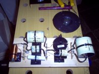
I use zip ties and tagstrip on a piece of timber. It's not a million miles away from Troels' ideas. And easy enough to change components.
Leave the component leads long until you finalise it. After all, there's always a bit of adjusting to taste. 🙂
Leave the component leads long until you finalise it. After all, there's always a bit of adjusting to taste. 🙂
Attachments

I went for the suggested flat on axis response after making my own frequency response measurements which turned out flatter than the factory curve and allowed for a flat voltage response for the RS52AN.
http://commanderlake.net/crossover/crossover.bpj
This is just the bandpass section for the RS52AN I'll have to put the highpass and lowpass on a second board.
http://commanderlake.net/crossover/crossover.bpj
This is just the bandpass section for the RS52AN I'll have to put the highpass and lowpass on a second board.
An externally hosted image should be here but it was not working when we last tested it.
Ooh wait. Noob mistake on coil alignment there.
Placement of coils in crossover networks
The significantly interacting coils should be at right angles.
Placement of coils in crossover networks
The significantly interacting coils should be at right angles.
Or there will be some induction effect so miniscule nobody could possibly hear the difference?
Just seen the link and wow thats hilarious, such a tiny effect wont make any audible difference, you "audiophiles" crack me up.
Just seen the link and wow thats hilarious, such a tiny effect wont make any audible difference, you "audiophiles" crack me up.
Last edited:
Just tested it with my own U1733C LCR meter and a 1.8mH coil, theres virtually no effect even when its touching another coil side be side and even on top of each other it only lowers the inductance by 50 MICRO Henry's, that difference doesn't even change the graph in the simulator.
It's not just the change in value that you need to be concerned about. try passing a reasonably high level signal through one and measure what is across the other one on a scope that may give you a more significant result.
My attitude is, that if it is not much extra effort to do it in a way that cannot cause problems then just do it, regardless of whether you think it will make a difference or not.
Tony.
My attitude is, that if it is not much extra effort to do it in a way that cannot cause problems then just do it, regardless of whether you think it will make a difference or not.
Tony.
Even if there is some inductive coupling there wont be anywhere near enough current to make a difference.
Have you seen the remark at the end of the page of TG :
a REAL problem IMHO, verified when I was tuning my last crossover for the combo CA22RNY/TW034.In my opinion, you measurements about the placement of coils won't show the whole truth or the real problem of placing coils next to each other. The real problem is the crosstalk, not the change in inductivity (although this is a little problem, too, even though the changes in inductivity stay below 10 %).
Can you see how much damping is in the parasitic loop?mark my words.
The response of the mid bandpass section is just as expected, if anything the high end slopes off slightly steeper but to the ear the high end doesn't seem to slope off as much as I would expect.
I just hope the peak at 12K wont be too much of a problem as it peaks just 13dB below the maximum amplitude point of the response curve.
Distortion is extremely low btw it slopes down very linearly toward the high end with no significant peaks.
I just hope the peak at 12K wont be too much of a problem as it peaks just 13dB below the maximum amplitude point of the response curve.
Distortion is extremely low btw it slopes down very linearly toward the high end with no significant peaks.
Last edited:
How are you measuring response and distortion?
Oh, and there's no discrimination here, people are trying to help, emphasis on the "if you're going to ask be willing to listen"
You've made a lot of mistakes, we know because we all made the same mistakes ourselves, it's a learning curve. 99% of the advise here is from people who don't want you to have to learn the hard way.... take the easy route when it's freely offered.
Just seen the link and wow thats hilarious, such a tiny effect wont make any audible difference, you "audiophiles" crack me up.
By audiophiles did you mean designers with considerable experience and knowledge? Wisdom can be an ellusive thing if you are not willing to listen 😉
Sorry but the crossovers turned out perfect and I felt offended by people saying they would sound terrible.
I use a calibrated SPL meter on dBc with c weighting correction in REW, the speaker is positioned in the center of the room (which has egg crate type sound insulation) with the SPL meter on a tripod 25cm at .7vRMS (as my bedroom is too small for a 1m measurement without room effects) from the driver for measuring the drive units individually.
I also tried measuring the speakers just 1-2cm from each driver to eliminate any phase or room effects to measure the response of the crossover which is flawless.
When you have a louder listening session you'll want to check the resistors for heat issues. The other components can get hot too, particularly the inductors but heat is primarily a resistance issue.
Sounds like you made good choices.All the inductors are 1mm wire and the resistors are 10w.
Resistors will only be '10W' when they have all around air flow. Mind the plastic cable ties.
The resistors are only on the mid and tweeter and I dont plan on blowing my ears out with treble so they should be fine.
Off the record I might agree. I sometimes use 1/4W resistors with tweeters.
They drum this kind of stuff into us pretty hard at college. Really try to put the fear of God into us.. voltage, charge, heat and so forth.
I'm sure it's saved my skin. I was the one who always built and presented the first working circuit in the class. Always copped some derision from somewhere over it too, lol. Good times.
Here's the response at 25cm random volume level aimed at the center of the speaker: http://commanderlake.net/response.7z (7-zip is required for those not familiar)
Last edited:
- Status
- Not open for further replies.
- Home
- Loudspeakers
- Multi-Way
- Designing a 4th order 3 way passive crossover