Hi All
I have decided to finally attemt an amplifier design by myself after a few diy builds from various members here, Carlos (Destroyer) and Ostripper.
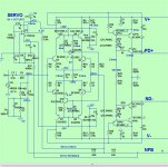
I designed and built a PCB which uses OStrippers output stage, and my own input stage, vas and thermal compensation.
Unfortunately when I power the amp through my test lamps, it seems I have some issue/s. R28 and R29 have an unsuspected 5v over them instead of millivolts and it cooks those resistors and blows a vas transistor or 2 as a result.
The design is attached below.


I have decided to finally attemt an amplifier design by myself after a few diy builds from various members here, Carlos (Destroyer) and Ostripper.
I designed and built a PCB which uses OStrippers output stage, and my own input stage, vas and thermal compensation.
Unfortunately when I power the amp through my test lamps, it seems I have some issue/s. R28 and R29 have an unsuspected 5v over them instead of millivolts and it cooks those resistors and blows a vas transistor or 2 as a result.
The design is attached below.
I would remove Q1 and Q2 as they overdrive Q3 and Q4 causing over-current on Q3 and Q4. Or remove the collectors of Q1 and Q2 and connect them to the next transistor Q3 and Q4 turning them into Darlington pairs.
I'm still trying to find the links ....
But complimentary differential topologies are inherently unstable with
current mirrors. (too much loop gain , like "opposed" Blameless's)
Many of our old "guru's" and even Cordell have explained why.
I did not go this route with my "spooky leach" .
Edit - in fact .. thermally - even beta enhancement at the VAS is overkill.
Low loop gain and a good Baxandall or Hawksford will give a stable result
with 20-30ppm 20k THD.
Edit 2 - Yikes ! you are even using beta enhanced mirrors !
OS
Last edited:
Hi Guys
Have you simulated this circuit?
It is more usual to use the 1381/3503 pair for the VA, since the dissipation can be a bit higher than what a TO-98 package is good for in free air. Similarly, the reverse diodes in the hum filters are larger types like 1N4007 rather than 1N914.
There might be an oscillation causing the Rs to burn up. Self found that fully complementary circuits like this with current-mirror loads were prone to high-frequency oscillation and to idling at much lower than expected VAS currents. The helper transistors in the CMs are supposed to take this a step closer to predictable performance.
It is also beneficial to add a resistor in the collector of the EF for the VAS. This limits its current and dissipation, and thus limits to some extent how how the VAS itself might get. I found this through experience in '92 or so.
Sometimes for these kinds of problems it is good to isolate the front end and just close the loop around it. You don't want to risk damage to all the expensive output stage silicon.
Have fun
Here is the original LTspice schematic.
View attachment Sim Amp mods.asc
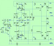
I will modify and post the new one when I try the new methods mentioned here to try fix this amplifier. Thank you every one for your suggestions so far. 1st I will try and remove q12, q15 to get a more simple VAS that looks like this.
View attachment Sim Amp mods2.asc
Simon
View attachment Sim Amp mods.asc
I will modify and post the new one when I try the new methods mentioned here to try fix this amplifier. Thank you every one for your suggestions so far. 1st I will try and remove q12, q15 to get a more simple VAS that looks like this.
View attachment Sim Amp mods2.asc
Simon
Oscillations is usually a sign of too much gain.
Fixes can be:
Larger cap at the VAS.
Remove extra gain stages.
Add base stopper resistors on driver and output stages.
If quasi then add BC 220pf at lower driver.
Fixes can be:
Larger cap at the VAS.
Remove extra gain stages.
Add base stopper resistors on driver and output stages.
If quasi then add BC 220pf at lower driver.
Here is the original LTspice schematic.
View attachment 548949
I will modify and post the new one when I try the new methods mentioned here to try fix this amplifier. Thank you every one for your suggestions so far. 1st I will try and remove q12, q15 to get a more simple VAS that looks like this.
View attachment 548951
Simon
Nope , High Z CM's(mirrors) will always "misbehave" from the cross conduction of a symmetric VAS.
- They even do worse things at clipping.
(Below #1-3) are the ones that have worked 2 years+.
#1- 53db 1K OLG ... #2- 53db .... #3 - 60db
#3 will clip like Valve (below 4).
Why do you think professor Leach never used a CM or beta enhanced VAS ?
PS - you don't need high gain (like a blameless) with this topology to get
descent THD. The design of the VAS is more a factor.
Edit - see how in your attachments you are degenerating your differentials (470R) , and
adding that crazy miller comp to both EF's in your VAS ?
That sort of nullifies any perceived gain added by the mirrors , huh ?
OS
Attachments

Last edited:
Not sure how you can expect a few millivolts across R28 and R29 .
Let's see R29 (R28 is symmetrical so basic same applies):
*IF* you have a few mV across R29 , and Q2 base is 2 diode drops (~1.4V) above it, then Vce across T4 is also ~ same.
My question is: does it work properly with such a small voltage?
Considering it also has 470 ohms in series with emitter.
I'd first check voltage drop across it, then substract 2 diode drops and calculate expected voltage across R29.
As in: I'd first check DC stability or values even before worrying about AC, gain, stability, etc.
Another worry: Q3/Q4 are small TO92 transistors, how much are they dissipating?
I don't know your rail voltages, although if you aim at 200/8 I'd estimate ~65V
...
which also makes me worry at T1/2/11/12 ... I'd be happier with higher voltage transistors there ... such as 2N5401/5551 which you are already using.
OK, hope you find your problem 🙂
I have decided to finally attemt an amplifier design by myself..
Really interested to know what was the motiv behind your decision. 😕
I simulated your circuit and it is supposed to be stable. You have plentiful phase margin and gain margin. There must have been something with the build, be it PCB, parts, or the assembly job that has gone wrong and smoked your VAS. The rail voltage in the schematic is +/-35V and using 2N5401/5551 for VAS is perhaps okay. Your starting post says 200w, if that is the case then better use KSC3503/A1381, like Struth suggests.
If you have double-checked all and ready for another try, perhaps try temporarily use a greater value resistor, like 1k/1W, as the VAS degeneration resistors, just in case you get an abnormal voltage there again, so that you at least have a chance to take voltage readings in the circuit long before any smoke comes out.
I changed a few components to their "usual" values when was in the LTspice,
--the emitter resistors at the EF preceding VAS changed to 1K to reduce the VAS current to 10mA from 13.7mA
--disconnected C6
--emitter resistor for predriver and dsriver transistors altered for a "healthy" standing current
--base stopper resistors for driver transistors changed to 10-ohm
I'd also recommend a CFP type bias control that works very well in my Meistersinger amp. The 2nd transistor in this circuit bleeds off "extra" VAS current and maintains a relatively constant current in the ThermalTack diodes, therefore, the OPS current is largely immune to the VAS current fluctuation that's often questioned about in a push-pull VAS without a current source defining its current. R23 is the pot for bias adjustment.
The Meistersinger, by the way, having complementary LTP input stage loaded with current mirrors and ThermalTrak output transistors, a similar but different design to yours, is a wonderful sounding amp. So I know this front end does work and works well when done right.
Attachments
Hi,
I suggest you strip out T3, T10 and T4, T9 and put in boring old resistors.
Reason being tht you have current mirrors on a pair of differential amplifiers. There is nothing in there that jumps out at me as defining the operating point.
OK, it might seem boring, but if you simply remove those transistors and put in simple old resistors (you need to work out the values you need here) you will then have a defined operating point which can be calculated from the bias current you se on the input differential pairs. I suspect that this is no small part of your issue.
Once you get things up and running, then you can start exploring more extravagant arrangements. But remember, heaping on lots of bits and masses of gain will increase your complexity and pain...
Where does it say that? 😕The rail voltage in the schematic is +/-35V
For 200/8 you need at least +/-60V (raw).
Have tried increasing cap to 100p at the VASOscillations is usually a sign of too much gain.
Fixes can be:
Larger cap at the VAS.
Remove extra gain stages.
Add base stopper resistors on driver and output stages.
If quasi then add BC 220pf at lower driver.
My decision was to try and learn something new. I am only a beginner at these things but enjoy learning and almost always bite off more than I can chew when doing projects, speakers, amps, woodwork. But it does help me learn sometimes when frustration subsides.Really interested to know what was the motiv behind your decision. 😕
Thanks for that it helps me that you posted your changes in the photo. I wold like the amp to eventually be 200-250w and am waiting for soft start boards to arrive. In the mean time I am using another amplifier (Blame ST) power supplies at +-35v to see iff the amp works or not.I simulated your circuit and it is supposed to be stable. You have plentiful phase margin and gain margin. There must have been something with the build, be it PCB, parts, or the assembly job that has gone wrong and smoked your VAS. The rail voltage in the schematic is +/-35V and using 2N5401/5551 for VAS is perhaps okay. Your starting post says 200w, if that is the case then better use KSC3503/A1381, like Struth suggests.
If you have double-checked all and ready for another try, perhaps try temporarily use a greater value resistor, like 1k/1W, as the VAS degeneration resistors, just in case you get an abnormal voltage there again, so that you at least have a chance to take voltage readings in the circuit long before any smoke comes out.
I changed a few components to their "usual" values when was in the LTspice,
--the emitter resistors at the EF preceding VAS changed to 1K to reduce the VAS current to 10mA from 13.7mA
--disconnected C6
--emitter resistor for predriver and dsriver transistors altered for a "healthy" standing current
--base stopper resistors for driver transistors changed to 10-ohm
I'd also recommend a CFP type bias control that works very well in my Meistersinger amp. The 2nd transistor in this circuit bleeds off "extra" VAS current and maintains a relatively constant current in the ThermalTack diodes, therefore, the OPS current is largely immune to the VAS current fluctuation that's often questioned about in a push-pull VAS without a current source defining its current. R23 is the pot for bias adjustment.
The Meistersinger, by the way, having complementary LTP input stage loaded with current mirrors and ThermalTrak output transistors, a similar but different design to yours, is a wonderful sounding amp. So I know this front end does work and works well when done right.
Where does it say that? 😕
For 200/8 you need at least +/-60V (raw).
LT spice file I posted has shown using 35v rails.
Hi Guys
I didnt get time today to do any changes or testing. The deign is basically a few ideas from Cordell's book cobbled together. It has become quite obvious that even though this models quite nice in LTspice, real world test is another thing. I would like to get this thing up and running eventually stubborness helps.
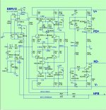
I have updated the LTspice file to match with the Eagle schematic so all components are the same Name.
View attachment Sim Amp mods 2.asc

I didnt get time today to do any changes or testing. The deign is basically a few ideas from Cordell's book cobbled together. It has become quite obvious that even though this models quite nice in LTspice, real world test is another thing. I would like to get this thing up and running eventually stubborness helps.
I have updated the LTspice file to match with the Eagle schematic so all components are the same Name.
View attachment Sim Amp mods 2.asc
Last edited:
Will have to have a look at that meitsinger amp.I simulated your circuit and it is supposed to be stable. You have plentiful phase margin and gain margin. There must have been something with the build, be it PCB, parts, or the assembly job that has gone wrong and smoked your VAS. The rail voltage in the schematic is +/-35V and using 2N5401/5551 for VAS is perhaps okay. Your starting post says 200w, if that is the case then better use KSC3503/A1381, like Struth suggests.
If you have double-checked all and ready for another try, perhaps try temporarily use a greater value resistor, like 1k/1W, as the VAS degeneration resistors, just in case you get an abnormal voltage there again, so that you at least have a chance to take voltage readings in the circuit long before any smoke comes out.
I changed a few components to their "usual" values when was in the LTspice,
--the emitter resistors at the EF preceding VAS changed to 1K to reduce the VAS current to 10mA from 13.7mA
--disconnected C6
--emitter resistor for predriver and dsriver transistors altered for a "healthy" standing current
--base stopper resistors for driver transistors changed to 10-ohm
I'd also recommend a CFP type bias control that works very well in my Meistersinger amp. The 2nd transistor in this circuit bleeds off "extra" VAS current and maintains a relatively constant current in the ThermalTack diodes, therefore, the OPS current is largely immune to the VAS current fluctuation that's often questioned about in a push-pull VAS without a current source defining its current. R23 is the pot for bias adjustment.
The Meistersinger, by the way, having complementary LTP input stage loaded with current mirrors and ThermalTrak output transistors, a similar but different design to yours, is a wonderful sounding amp. So I know this front end does work and works well when done right.
Which resistors do you think needs changed to 1k? R9, 17, 7, 18 (new updated ltspice file).
View attachment Sim Amp mods 3.asc
Last edited:
Will have to have a look at that meitsinger amp.
Which resistors do you think needs changed to 1k? R9, 17, 7, 18 (new updated ltspice file).
View attachment 549088
It was R26/R27 that I would reduce to 1K from 1.5K to bring down the VAS current from 13.7mA to 10mA.
And it was R28/R29 that I was suggesting temporarily be substituted with 1K/1W just for troubleshooting purpose.
But why on earth recycling old chew-in spit-off topology, there's nothing new to learn about. I'm really getting sick viewing the same old crap in almost every new thread started here. Apologize for the rough words, but absolute true.My decision was to try and learn something new. I am only a beginner at these things but enjoy learning and almost always bite off more than I can chew when doing projects, speakers, amps, woodwork. But it does help me learn sometimes when frustration subsides.Really interested to know what was the motiv behind your decision. 😕I have decided to finally attemt an amplifier design by myself..

Suggest you write such data on the visible schematic itself, it's the first anybody checks.LT spice file I posted has shown using 35v rails.
Whether opening it or not in a simulator is an optional step.
That said, unfortunately have to agree with lazy cat's words, harsh but true.
One unexpected byproduct of Bob Cordell's excellent book is that everybody and his brother feels he's now a 5 minute wonder and entitled to "design" .... which would be fine if it actually involved designing.
I mean starting with datasheets and a clean sheet of paper.
FWIW randomly cutting and pasting together random snippets picked here and there do not count as such, sorry.
And successfully simulating, although a powerful and useful tool, is still far away from real world construction and functioning.
Sorry.
As a counter example, some designs, such as popular apex audio ones, may not look as fancy as some of the book examples, but are very good in practice, and *do* work as promised , in great part because of Mr Apex considerable experience actually building and delivering them for many years.
Niss , just go modular.
Build a good output stage , recycle every "spit-off" topology you can ....
you might find one you like.
OS
Build a good output stage , recycle every "spit-off" topology you can ....
you might find one you like.
OS
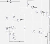
Today I simplified the VAS as sugested. Removed Q1 and Q2 and R26, R27 Linked the base to emiters of q1 and 2 to get a simple VAS. I then removed 2nd power stage transistors Q19 and Q20 (mje15032,33) to protect output power transistors. Then removed 1 leg of R39 resistor and added a second r39 linked at a common end to create a new common point for the negative feedback wire.I would remove Q1 and Q2 as they overdrive Q3 and Q4 causing over-current on Q3 and Q4. Or remove the collectors of Q1 and Q2 and connect them to the next transistor Q3 and Q4 turning them into Darlington pairs.
Is this the usual method for removing the output stage and just testing the input, or are there other methods to do so?
Anyway, the result was a stable input stage. Voltages with a link on the input are testing the same as Ltspice is predicting with the current Circuit. What do you guys suggest as the next step now? Change the VAS to a different design again, or re install the output stage with this simple VAS installed?
Anyway, current schematic and changes are shown below.
Niss , just go modular.
Build a good output stage , recycle every "spit-off" topology you can ....
you might find one you like.
OS
Yeah. I really like your idea of doing that. Smart idea when doing many designs such as you like to do.

Upon checking the previous vas resistors R28,R29 they now start off at 150mv across the resistors and climb very slowly over a matter of minutes now at 260mv after around 4 minutes and continuing to rise slowly. Now sure what is causing this, maybe still oscillations but now to a lesser extent?
- Status
- Not open for further replies.
- Home
- Amplifiers
- Solid State
- Designing 200w Amplifier. Oscillations or something else? need help please.