Hello Everyone!
I would like to share with you the concussions of a study I have been working on over the past months to design an optimised 3D printed port for a desktop loudspeaker. I tested various methods to reduce unwanted resonances, while keeping an eye on port turbulence.
EDIT 22/04/24: The design study has been significantly revised to include more information and correct some erroneous conclusions.
3D Printed Loudspeaker Port Design Study V2

Original post:
3D Printed Loudspeaker Port Design Study < Clicky Click
Here are a few snap-shots:


There is a whole lot of info in the paper beyond this including the effect of holes in ports, reduced wall thickness, constrained layer damping and what bending ports does to the response. I encourage you to check it out, since it took me a lot of work")
While I unveil the fruits of the efforts, I must confess I have the intention of eventually offering a DIY kit and a finished product for sale based on the methods revealed in this study. I hope this doesn't detract from my wish as a fellow enthusiast to share what I discovered.
Thanks also to @stv for encouraging me to make the effort writing up what I was doing. His thread on port resonance is a gold mine. Also thanks to @andy19191 for early feedback on the document.
Simon
I would like to share with you the concussions of a study I have been working on over the past months to design an optimised 3D printed port for a desktop loudspeaker. I tested various methods to reduce unwanted resonances, while keeping an eye on port turbulence.
EDIT 22/04/24: The design study has been significantly revised to include more information and correct some erroneous conclusions.
3D Printed Loudspeaker Port Design Study V2
Original post:
Here are a few snap-shots:
There is a whole lot of info in the paper beyond this including the effect of holes in ports, reduced wall thickness, constrained layer damping and what bending ports does to the response. I encourage you to check it out, since it took me a lot of work
While I unveil the fruits of the efforts, I must confess I have the intention of eventually offering a DIY kit and a finished product for sale based on the methods revealed in this study. I hope this doesn't detract from my wish as a fellow enthusiast to share what I discovered.
Thanks also to @stv for encouraging me to make the effort writing up what I was doing. His thread on port resonance is a gold mine. Also thanks to @andy19191 for early feedback on the document.
Simon
Last edited:
I would like to share with you the concussions of a study I have been working o
Studying ports is tough but not that tough!
I had some thoughts on this from my previous experience with calming the turbulence a vessel was creating, but then I gave up on ports to explore a different angle to both pots and PR while remaining in a reflex system. Appears that my ramblings are often ignored but if anyone is interested in brainstorming this from a concept to working prototype level than please feel free to open a more private dialogue
Tenson,
Nice write up!
You might want to review the reference to the Dayton Audio ND91-4 where you write "The high cone excursion of 25 mm peak".
The ND91-4 specifications list it has a voice coil diameter of 25mm, an Xmax of 4.6mm (9.2mm peak to peak).
It is possible that Xlim/Xmech might be 12.5mm (25mm peak to peak) but considering 2nd harmonic distortion at 80Hz in the sealed box at 8.7volts was about -18dB (~13%) looks like it reached or exceeded Xmax at ~90dB at 1meter.
Port resonance problems are a tough nut to crack, interesting to see the results between the "baseline" and "optimised".

Reducing the out of phase 600Hz port resonance reduced the cancellation notch there, while increasing the problem at 900Hz.
Not a bad trade.
Why did you use 2mm stainless steel for the rear panel?
Art
Nice write up!
You might want to review the reference to the Dayton Audio ND91-4 where you write "The high cone excursion of 25 mm peak".
The ND91-4 specifications list it has a voice coil diameter of 25mm, an Xmax of 4.6mm (9.2mm peak to peak).
It is possible that Xlim/Xmech might be 12.5mm (25mm peak to peak) but considering 2nd harmonic distortion at 80Hz in the sealed box at 8.7volts was about -18dB (~13%) looks like it reached or exceeded Xmax at ~90dB at 1meter.
Port resonance problems are a tough nut to crack, interesting to see the results between the "baseline" and "optimised".
Reducing the out of phase 600Hz port resonance reduced the cancellation notch there, while increasing the problem at 900Hz.
Not a bad trade.
Why did you use 2mm stainless steel for the rear panel?
Art
Last edited:
Whoops, must have gone cross-eyed reading the xmax figure! I'll update that, thanks.
The rear panel is 2mm stainless because it will support connectors and electronics eventually. The front is glued on, so at least the back should be removable.
Yes the box is damped in all cases.
The rear panel is 2mm stainless because it will support connectors and electronics eventually. The front is glued on, so at least the back should be removable.
Yes the box is damped in all cases.
Interesting little speaker:
https://www.parts-express.com/pedocs/specs/290-224-dayton-audio-nd91-4-klippel-test-results.pdf
https://www.parts-express.com/pedocs/specs/290-224-dayton-audio-nd91-4-klippel-test-results.pdf
I would never have guessed CLD would be the most effective. So it isn't simply the air in the pipe taking part in the resonance, but it gets some support by the characteristics of the wall? I suppose the Kef port kind of points to this but when I tried to copy it the results showed some small benefit but nothing to get excited about.
I don't quite understand the wall thickness tests. You only thinned a small hexagon shape in the center of the port? Why not the entire wall at the center?
I don't quite understand the wall thickness tests. You only thinned a small hexagon shape in the center of the port? Why not the entire wall at the center?
I suppose it highlights that nothing is perfectly stiff, everything is elastic especilly when resonance shows its face. The ports all feel quite sturdy to the touch.
Regarding the reduced thickness, I already tried a full thin wall and it was terrible so I knew there are limits. I didn't make it the full width of the port because I wanted to keep some structural connection between the top and bottom parts of the wall. Width of the area is 40 mm out of 100 mm.
Regarding the reduced thickness, I already tried a full thin wall and it was terrible so I knew there are limits. I didn't make it the full width of the port because I wanted to keep some structural connection between the top and bottom parts of the wall. Width of the area is 40 mm out of 100 mm.
I would never have guessed CLD would be the most effective. So it isn't simply the air in the pipe taking part in the resonance, but it gets some support by the characteristics of the wall? I suppose the Kef port kind of points to this but when I tried to copy it the results showed some small benefit but nothing to get excited about.
It appears to be a tuned absorber where the energy in the acoustic resonance drives bending in the port which is absorbed by the damping layer. I would expect a combination of mass, stiffness, damping and geometry that works well to involve a fair degree of design effort. A degree of luck may have been involved in this respect.
A port that is flapping around will be generating unwanted sound (as will the cabinet) which will be showing up as the sound that isn't from the Helmholtz resonance, the acoustic modes in the port or the aerodynamic noise from turbulent vortex shedding which all have expected behaviours. How much of this should be traded? The acoustic modes within the cabinet are also likely having an influence given the dimensions. Correctly identifying and quantifying the relevant physics is far from straightforward without simulations that capture the relevant physics.
I think the extremely high level of damping makes application easier than one might expect for a 'tuned absorber' since the Q will be low.
The CLD port does show slightly higher turbulent chuffing noise than the baseline port and focused where the frequency of the resonance peaks are (1 KHz - 2KHz). Interestingly addition of the thin wall section did not increase this, if any reduced it slightly. I wonder how much is noise due to flexing of the port walls disturbing the air motion and how much might be the two layers of wall touching / rubbing on each other especially if there were small gaps (I did my best to ensure a complete bond). It will be interesting to see if a slightly thicker damping layer reduces that noise region.
I should have the opportunity in the future to try this on a larger cabinet and port with round or oval cross-section shape.
Last edited:
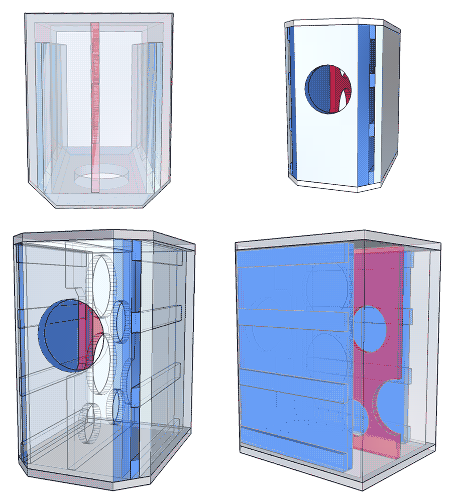
Using this picture for an easy visual reference (thanks weltersys), we can see the 600hz resonance is gone, but we have two variables.
1. The port is changed.
2. The port opening location is changed.

How confident can one be of the conclusion that the elimination of the 600hz resonance is due to variable 1, but not variable 2?
If the driver was placed symmetrically in the box, orientation of the port opening (top vs bottom) wouldn’t matter, but with the asymmetric location of the driver, nodes/antinodes will also be different throughout the box. Perhaps one port location was where there was a 600hz node, but not in the other?
1. The port is changed.
2. The port opening location is changed.
How confident can one be of the conclusion that the elimination of the 600hz resonance is due to variable 1, but not variable 2?
If the driver was placed symmetrically in the box, orientation of the port opening (top vs bottom) wouldn’t matter, but with the asymmetric location of the driver, nodes/antinodes will also be different throughout the box. Perhaps one port location was where there was a 600hz node, but not in the other?
That's a very good point, the driver is slightly off centre on the height of the baffle. I tried flipping the baffle 180 degrees quite a long time ago and saw only minor changes. That was before I started taking it seriously to document everything.
I don't think the response is entirely dictated by the port shape there does seem to be a cancelation going on on the right hand graph. Perhaps as the length of the port and the cabinet are similar they interact.
I should note the entrance to the ports is all in the same location other than the inversion vertically.
This is why I dont like ported box 2 ways. The midrange always gets screwed up no matter how hard you try to reduce out of band port output. With some brain storming, there has to be another more effective way to deal with this problem.
I was always under the impression based on my experiences trying to clean up unwanted port output, the best compromise was to use the shortest and smallest surface area possible with strategic dampening material used immediately behind the driver to reduce rear midrange leakage. The argument was to avoid exciting the resonances by not exciting them at all (or practically speaking, as little as possible).
There must be a way to avoid slowing down the air velocity and hurting tuning efficiency. Also, the use of a dual chamber reflex construction could filter much of the midrange out acoustically by the time the fundamental port output reaches the second chamber. DCRs can be very effective here and also improve midbass performance.
Perhaps the least lossy way to filter most of the midrange junk while not suppressing the helmholz resonance too much is using a separating passive diaphragm inside the enclosure, just out of direct line of rearward fire of the bass-mid driver. This way much of the rear radiated midrange energy is considerably attenuated by the time the fundamental pressure waves reach the port area. A single external passive radiator may be easier to implement at this point, so maybe that's just an overcomplication.
Using some clever U-shaped baffling, surrounding most of the back side of the bass-mid, helps alot. This is how I deal with the issue in a larger 2 way. It works very well if the dampening material is of sufficient thickness to absorb the middle wavelengths. This would be much harder with smaller compact designs, which are by far the hardest type of ported enclosure to design with very clean midrange.
I've also used insulating EPDM foam rubber around port tubes drilled with many smaller holes, achieving very clean port output with little junk emitted above 300 hz or so. The foam layer retains the slower fundamental resonances, keeping them from leaking out of the port perforations, thereby retaining efficiency but attenuating the higher midrange resonances from the port. The holes covered with the foam are more lossy to higher frequencies, allowing those pressure waves to react and be absorbed while being mostly inert to the longer fundamental wavelengths. This way it dampens only the higher mids in the tube. The foam also dampens the structure born surface resonances of the port tube. Different materials with different dampening characteristics can be substituted with better results depending on desired bandwidth and port dimensions, so further experimentation may reveal improved results.
This is why I dont like ported box 2 ways. The midrange always gets screwed up no matter how hard you try to reduce out of band port output.
Given your objection, you would expect the FR boxes i do to have greater issues with the same thing. They do not — the midrange is very good without any real resonace issues.
dave
- Home
- Loudspeakers
- Multi-Way
- Design Study of 3D Printed Loudspeaker Port