Are you planning to share a power supply for the monoblocks?
If so, i’d be interested in how you plan to connect the units. I have a similar plan I am hatching, but more modest: two Quad 2 clones (using EF40 and 5B/255M to stay NOS and affordable) but sharing a common power supply.
If so, i’d be interested in how you plan to connect the units. I have a similar plan I am hatching, but more modest: two Quad 2 clones (using EF40 and 5B/255M to stay NOS and affordable) but sharing a common power supply.
I've poorly explained the whole business about the 10R resistor, but I'll try a better summary tomorrow. The intent is to float input signal ground slightly away from the inherently noisier big signal ground, and to minimize messiness of the commonality of shield and signal return of unbalanced interconnects. This isn't the end of life as we know it, but can be a simple and worthwhile improvement that won't show up in simulations. Strictly real-world.
If you worry about overhead space for your input stage CCS, it could possibly be brought from the bias supply. Plenty of voltage there.
At some point, you'll want to choose a spot to place your low frequency dominant "pole". The circuit has three LF "poles" (actually, zeros, but you know what I mean): the two coupling caps and the output transformer's primary (shunt) inductance. The OPT itself is the worst choice for several reasons. Some recommend the first capacitors, which gives the best headroom in the driver stage. I prefer the second capacitors, which minimizes "hang time" following overload, and just make the driver stage robust. Your choice, of course. But you don't want both time constants so similar. 4Hz to 8Hz open-loop suits good quality OPTs.
Wonderful project, and all the best fortune,
Chris
With 500V B+ and 80mA quies that will drive the UL output stage fairly hard with today's tubes (near cherry red anodes). On paper I'd expect closer to 50W output not 30W.
On bench lines; A 3 stage 100W amp is in development = tube line up, 6CG7 (alias 6SN7) front end: 12BY7's as triode drivers paralleled, feeding 3x 6550 each p-p half. More later.
rJ
On bench lines; A 3 stage 100W amp is in development = tube line up, 6CG7 (alias 6SN7) front end: 12BY7's as triode drivers paralleled, feeding 3x 6550 each p-p half. More later.
rJ
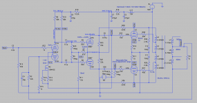
Hi Hector, I'm planning on building this as two mono blocks, each with a separate power supply on the same chassis as the amp, not shared.
Chris, yes, I know I didn't do exactly what you explained. The 10 ohm resistor I have in there seems to be necessary for stability, even in the simulator, though. I need to look at this a little more and get a better grasp on it. I still have more work and research to do, thank you for the help so far.
Rich, that sounds like one powerful amp. I probably can get more power out of it if needed or if I went with a 4K transformer, but I'm not too concerned with the output power. I think this should design should keep it more on the class A side. I've posted the curves I plotted for this, I'm not 100% certain that I did this correctly in LTSpice, particularly on the AB slope, if anyone can verify.
Tikaroo, the latest LTSpice file is attached. I forgot to update the power supply resistors in the last PDF. Let me know what you think.
John
Attachments
Chris, yes, I know I didn't do exactly what you explained. The 10 ohm resistor I have in there seems to be necessary for stability, even in the simulator, though. I need to look at this a little more and get a better grasp on it. I still have more work and research to do, thank you for the help so far.
Rich, that sounds like one powerful amp. I probably can get more power out of it if needed or if I went with a 4K transformer, but I'm not too concerned with the output power. I think this should design should keep it more on the class A side. I've posted the curves I plotted for this, I'm not 100% certain that I did this correctly in LTSpice, particularly on the AB slope, if anyone can verify.
Tikaroo, the latest LTSpice file is attached. I forgot to update the power supply resistors in the last PDF. Let me know what you think.
John
Last edited:
Hi Hector, I'm planning on building this as two mono blocks, each with a separate power supply on the same chassis as the amp, not shared.
Chris, yes, I know I didn't do exactly what you explained. The 10 ohm resistor I have in there seems to be necessary for stability, even in the simulator, though. I need to look at this a little more and get a better grasp on it. I still have more work and research to do, thank you for the help so far.
Rich, that sounds like one powerful amp. I probably can get more power out of it if needed or if I went with a 4K transformer, but I'm not too concerned with the output power. I think this should design should keep it more on the class A side. I've posted the curves I plotted for this, I'm not 100% certain that I did this correctly in LTSpice, particularly on the AB slope, if anyone can verify.
Tikaroo, the latest LTSpice file is attached. I forgot to update the power supply resistors in the last PDF. Let me know what you think.
John
Yes John, I made a mess of previous post quote etc, as an ex upstream oil worker with rather large fingers I make loads of typo errors.
-----
Your design deviating just a scrape away from AB; the o/p stage runs quite hard. As for the 10R resistors in the output stage, I put them in each leg or commoned they should slightly lower distortion; whether SPICE will show this up remains to be seen. Also the 10R should be a wirewound as MF types are pretty hopeless in dealing with power transients and will gradually go open.
As to my design, the 6x 6550' ( I have a lot of boring looking clear glass B types with pellet getter) poses it's own problems as these are soft tubes and require hard drive to run in fixed bias with lower value grid leak resistors. I might use choke coupling, but to be determined. Various vendors 6550B behave differently; the worst issue is very slow tube settling time from the heater switch-on. One gets the impression the heater is at the incorrect voltage, but not so.
With B+ slightly over 400V, this is a modestly run amp but my main objective is to determine sound quality with UL at 20 or 40%. O/P tranny a custom speck'd well balanced 1.25KA-A Williamson design by Majestic transformers UK.
This old company still designs and remakes...bear in mind winding tube output transformers is a work of art from previous generations that are gradually on their way out.
THD on these designs and yours should be way low; square wave response good and sharp even at 10Khz but Spice cannot determine this, as so much depends on the O/P tranny parasitics. One should be looking at 0.1% thd or less at 1Khz full power with modest 15-20dB global feedback.
More anon
yozurs
rich
Fiatguy85 - Your output transformer model was out by a factor of 10 for impedance ratio, I've adjusted the inductances based on a model for a 5k Hammond 1645. I've also shown DC coupling between the first and second stages with some adjustment in operating points to allow this. Took the first stage CCS to the negative rail and replaced the second stage CCS with a resistor (don't really need a CCS here). Reduced the local feedback ratio and increased the global NFB a bit. Dropped the KT88 bias current to reduce total dissipation to about 30W each. As shown will do 50+ watts at around 0.1% THD. I'm sure there's still plenty of refinements to be made.
Attachments
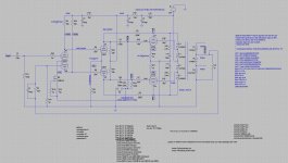
On second thoughts DC coupling is a bad idea with this topology has it only works in SPICE where the first stage anode voltages are equal 😱. In real life they won't be. Other changes should still be OK 😀

Hi OldHector,
It’s a pity to see all the cathode decoupling cap’s. In testing and measuring a somewhat similar topology I tried these too, but it’s better to leave them out. Better frequency response, lower distortion, etc..
Regards, Gerrit
It’s a pity to see all the cathode decoupling cap’s. In testing and measuring a somewhat similar topology I tried these too, but it’s better to leave them out. Better frequency response, lower distortion, etc..
Regards, Gerrit
Hi Hector,
If there's anything I've learned researching this project, it's that there are very few original ideas! Thank you for the schematic, it's always helpful to see where other people ended up and that you're going down a sensible path.
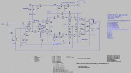
Tikiroo, you have bested me at my own game. I agree the second CCS is not necessary, and your other tweaks have much improved the performance. I must have been having a bad math day when I did my transformer calculations. I played around with it a little while and I don't honestly know how to improve it much more.
I made a couple minor tweaks which might have flattened the response and optimized the distortion, but only very slightly. I'm going to have to ponder this over a bit and see what else I can learn, and I'm open to suggestions.
Also, if there are any practical suggestions for the construction that might be useful to incorporate into the schematic, I'd appreciate those. This will be my first PP tube amp, so I have a ways to go. I will play around a little more and update the PDF after a little while.
John
If there's anything I've learned researching this project, it's that there are very few original ideas! Thank you for the schematic, it's always helpful to see where other people ended up and that you're going down a sensible path.
Tikiroo, you have bested me at my own game. I agree the second CCS is not necessary, and your other tweaks have much improved the performance. I must have been having a bad math day when I did my transformer calculations. I played around with it a little while and I don't honestly know how to improve it much more.
I made a couple minor tweaks which might have flattened the response and optimized the distortion, but only very slightly. I'm going to have to ponder this over a bit and see what else I can learn, and I'm open to suggestions.
Also, if there are any practical suggestions for the construction that might be useful to incorporate into the schematic, I'd appreciate those. This will be my first PP tube amp, so I have a ways to go. I will play around a little more and update the PDF after a little while.
John
Attachments
Last edited:
Looking good. I would worry about 1M Ohm grid leak resistors with any modern output valves, especially without cathode bias. 0M1 Ohm would be much safer, and no real problem for your driver stage. Coupling caps here would be 0u1 F for an 8Hz pole, 0u22 F for a 4Hz.
If your sims program can plot frequency magnitude and phase response down into the infrasonics you may be able to crudely model these choices, but aren't really trustworthy. OPT primary (shunt) inductance varies dramatically with signal level, and in the direction of decreasing stability with increasing signal level. DTN Williamson, in the follow-up to his original paper, discussed this issue very well and is well worth reading.
He came to the conclusion, and who am I to argue, that a dominant RC "pole" significantly above the OPT's RL "pole" at idle was the clear design choice.
All good fortune,
Chris
I’ve found with Hammond output iron that you obtain a more stable amp by tapping the global feedback signal from the 4 ohm tap rather than the 8 ohm tap. That assumes the original style secondary connections on the Hammonds. If you’re using the “easy wire secondary” models it may work great tapping the feedback from the 8 ohm tap.
But all that will need to be worked out on the bench when you test for stability after closing the global loop.
But all that will need to be worked out on the bench when you test for stability after closing the global loop.
Last edited:
Use a pair of pentodes instead of the 6SN7. 6AQ5 should do; you'll not need much gain with that 12AY7 up front. Also, since you will get all the FB the E-Linear design is capable of, you can do away with the loop of NFB.
cheers,
Douglas
cheers,
Douglas
Hector, I finally read through the 88-50 article you linked and it is helpful in explaining the stabilizing circuits a bit more, thank you!
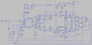
Chris, I am able to model the frequency magnitude and phase response in LTSpice. I went to 100k on the grid leak resistors for the KT88.
I added the dominant pole and I have also increased the value of the coupling caps. My observation was that the higher value coupling caps decrease the phase shift at low frequency.
Attachments
- Home
- Amplifiers
- Tubes / Valves
- Design Feedback - KT88 PP UL 30W