Consider yourself lucky with that repair.It's a piece of cake fix and you can score brownie points with friends & family with free subs!
Most powered subs that fail are a PIA to fix since the schematic isn't usually available.
The newer Polks are SMPSs, and they fry pretty much irreparably. When caps go bad on an old school supply it’s a soft fail that doesn’t take anything out with them.
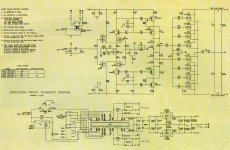
One I really like is found in the Hafler 9500, which has four pairs of MOSFETs on each output driven by (drumroll please) four TO-92 transistors, MPSA56 and MPSA06. The poor little buggers get kind of warm, as in toast-the-motherboard warm, and eventually the amplifier starts popping large DC surges through the speaker when the drivers start losing their grip after a few hundred hours of this abuse. Somebody figured they could run silicon at 100C forever, surprise!
It otherwise sounds reasonable, pity about the design fail.
It otherwise sounds reasonable, pity about the design fail.
Attachments
That’s what the MPSU versions were supposed to be for - a full watt of dissipation and a bit more if you bolted the tab to something. They were available back then, even if long gone now. Modern TO-126’s would work just fine to keep it from toasting.
I still have a whole $#*+load of MPSU56’s, but unfortuately no 06’s.
I still have a whole $#*+load of MPSU56’s, but unfortuately no 06’s.
New parts in place, stood up off the PCB for air circulation, and make-shift heatsinks added to transistors:

Circa 1990 I had a Technics RS-1500 reel-to-reel, a really nice deck. I noticed as I turned the playback level past 2 or 3 o'clock some distortion that increased as I continued to turned it up. This seemed odd on such "good" equipment, and I checked my amp to make sure it wasn't distorting with other sources at the same signal level. I don't remember having the schematic, but I opened it up and looked at the PC board around the output level control. I found two diode-connected transistors between each control wiper connection and ground. I wondered what in the world that could be there for, but I removed them (I don't remember if they were on the solder side or the component side), and that fixed it. I can't imagine why that would have been there.
I put on my dental loupes and reworked the solder joints (and several others) that people pointed out and got them all nice and shiny.
When I finished I put it all back together, hooked it up and discovered the right channel was dead. I had a momentary panic attack and reopened the amp and discovered that one of the very short wires that connect the speaker binding posts to the PCB had broken due to being flexed one too many times. I replaced all four wires and put heat shrink over the ends that connect to the binding posts and there were no more problems.
One thing I found that could be considered a design/manufacturer defect was the use of 32V 12A fuses on the power supply rails (75VDC). I replaced those fuses with 250V 12A parts.
Blog post here.
"One thing I found that could be considered a design/manufacturer defect was the use of 32V 12A fuses on the power supply rails (75VDC). I replaced those fuses with 250V 12A parts."
That 32V rating was for DC, however the 250V rating is for AC. You would have to check with the mfr to see if there is a DC rating.
That 32V rating was for DC, however the 250V rating is for AC. You would have to check with the mfr to see if there is a DC rating.
- Home
- Amplifiers
- Solid State
- Design errors in commercial equipment


