"The only tube that I have in mind for this kind of amp is the EL509, rated for 1.4A max but dissipation is about 40W, calculating a 500W dissipation I need at least 12 tubes (six couples)."
If psu is +-300v, 1.4A each for 12 tubes this is 16.8A peak, total power in=300x16.8=5KW, minus 600W output still 4.4KW tot tubes dissipation, not 500W.
EL509s are rated for 1.4A max, 1.4A is not the quiescent current, quiscent current will be much lower!
So, I'm thinking about an OTL mixed transistor driver/output tubes...
I found the Shuguang 805 tubes, with 1.5kV and four or six of this tubes I can obtain about 600W, anyone know how reliable are they.
Directly heated triodes in an OTL design @ 300kHz? Forget about it!
Best regards!
Directly heated triodes in an OTL design @ 300kHz? Forget about it!
Best regards!
No, 805 is for PP with more than one transformer... sorry for my bad writing 🙁
Choice 1: OTL with mixed transistors/tubes.
Choice 2: PP with more than one output transformer.
EL509s are rated for 1.4A max, 1.4A is not the quiescent current, quiescent current will be much lower!
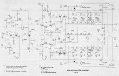
Peak, not quiescent. This happened when the load is low. Even at 96 ohms it's 2.5A rms, 300x2.5x2=1500W-600W, but I suspect it's more as I doubt you can swing out 240V rms with +-300V, I suspect could be higher. Alan's OTL (attached) use +-180V, but into 4-16 ohms and more complex in the output as the argument or boosted Vg2 circuit you have you put up when even more power is wanted.
Attachments
Last edited:
For 600 Watts output at 96 Ohms, that will require 240 Vrms, or 339.4V peak. With 60V drop on the pentode EL509 type tubes, that means B+ has to be at least 400V. Peak current then is 2.5Arms or 3.53 Amps peak. Tube diss. then is 60V x 3.53A = 212 Watts. Divide by 6 tubes gives 35 Watts per tube. (but 1/2 the time)
But max tube diss. occurs near 170V peak output with 1.77 Amps. So tube diss. then is at 400V-170V= 230V and 1.77 Amps. So tube diss. is 230V x 1.77A = 407 Watts, divide by 6 tubes giving 68 Watts per tube! (well, that is peak power diss., time averaged over both tube banks would cut that by 1/2 to 34 Watts per tube)
Some additional tubes needed for safety factor still. (70% utilization safety factor -> 9 pairs)
All this to avoid 2 or 4 Mosfets?
You could put some darn'd impressive protection circuitry around the Mosfets for that $$$.
.
Last edited:
Thank you very much for your suggestions and congratulation for your power amp! It looks great!
So, I'm thinking about an OTL mixed transistor driver/output tubes, I need +-300V B+ power supply (or 350 to stay safe) because power pentode or tetrode usually have a minimum of 50V Vak when Vg=0V.
The only tube that I have in mind for this kind of amp is the EL509, rated for 1.4A max but dissipation is about 40W, calculating a 500W dissipation I need at least 12 tubes (six couples).
I think it is also possible to use two or more transformer with different frequency bands.
I found the Shuguang 805 tubes, with 1.5kV and four or six of this tubes I can obtain about 600W, anyone know how reliable are they?
This is only an experiment to see if tubes can be useful today, I know that I can design the same with MOSFET (I don't know if SiC can be used for linear applications) but we want to see if tubes have some advantages, I know that transistor is a better choice but the chief want to experiment with tubes, for me is an occasion to get fun.
Maybe after experimentation phase all the stuff will be throw in the rubbish.
What is the LOAD Z WRT FREQUENCY??
How can you "design" something not knowing this??
Not sure there is a load outside a resistor that is flat across that range??
AND, just what is the nominal load Z?
So, you want to use 805s? Sure if you've got a high Z load - like an RF amplifier? Are you making an RF amplifier or an audio power amplifier.
Nobody is getting out to 300kHz with an output transformer of any size, unless you've got some stuff from Roswell sitting around, eh?
So what the heck are we driving to what with?? Otherwise why muck about with conjecture about something that has no parameters...
EDIT: ok stop mucking about and buy up some Ruskie 6C33C tubes and go OTL, just watch out for the load Z that it doesn't dip too low...
You obviously are looking for current, so that's the way to go. Done.
> I need a lot of matched pieces
If you use "a lot" of devices parallel, matching gets far less important.
> if tubes have advantages in robustness against BJT and MOSFET.
This battle was lost long ago for many reasons. Transistors got better. Complex transistor protection systems got mature and affordable. A particular trend is the constantly declining prices of transistors. Where we used to struggle to afford two devices for a 75W amp, it is now economic to use eight devices (the heatsink is less massive). OTOH tubes have got worse, being a low-volume specialty market which is ruled by lowest-bidders.
And a basic "reliability" concept widely ignored in electronics-- OVER-build!!
Houses and bridges do not fall down, much, because they are designed with a Factor Of Safety of at least 4:1. If a beam might have a 1000 pound load, we use a stick that will not fail at 4000 pound stress. In houses, we use wood which lab-tests at 3000psi but design as if it were 1000psi wood. Then we use a very high number for possible floor loading. The result is that most houses live their lives with greater than 4:1 factor of safety. My power line is rated for 95 Amps, fused for 100 Amps, but would sustain 900 Amps for many seconds, 200 Amps for minutes, and then fail "gracefully" (no deaths, easy to repair). FWIW, I never get near 95 Amps.
The FoS varies with application: airplanes lean to 2:1 and spaceships even less, overhead lifting usually specifies FoS of 10:1.
So if you want 600 Watts, be SURE it is NEVER more than 600 Watts, then build a 2,400 Watt amplifier. It will loaf even if you estimated load is much more than you think it will be.
2,400 Watts is ordinary transmitter tubes, which are still available in some quantity at good quality. Two 4-1000A will do it, but the 4000V supply and 7Kpp load are daunting.
"Audio" bandwidth is inverse to winding impedance. We can make a really wideband 100 Ohm winding. At 7,000 Ohms the parasitics make even 30KHz tough. Since tubes like to see thousands of Ohms, this leads to a massive parallel connection. Which also improves reliability (a 7-pair amp will "work" with 13 tubes) and makes "matching" less important. (But don't know what you are matching if distortion is unimportant and you work deep-B.)
Last edited:
For 600 Watts output at 96 Ohms, that will require 240 Vrms, or 339.4V peak. With 60V drop on the pentode EL509 type tubes, that means B+ has to be at least 400V. Peak current then is 2.5Arms or 3.53 Amps peak. Tube diss. then is 60V x 3.53A = 212 Watts. Divide by 6 tubes gives 35 Watts per tube. (but 1/2 the time)
But max tube diss. occurs near 170V peak output with 1.77 Amps. So tube diss. then is at 400V-170V= 230V and 1.77 Amps. So tube diss. is 230V x 1.77A = 407 Watts, divide by 6 tubes giving 68 Watts per tube! (well, that is peak power diss., time averaged over both tube banks would cut that by 1/2 to 34 Watts per tube)
Some additional tubes needed for safety factor still. (70% utilization safety factor -> 9 pairs)
All this to avoid 2 or 4 Mosfets?
You could put some darn'd impressive protection circuitry around the Mosfets for that $$$.
.
I think this sims are pretty close to your calculations. This is based on Circlotron clone by Patrick. Will 6c33c or el509 withstand 400V on the plate?
Attachments

Last edited:
Your only real hope for that wide a bandwidth is with a nanocrystaline core, single layer primary and secondary toroid and likely with both windings segregated into discrete sectors. Most likely on a 1 Kva core size. Use of a film tape dielectric will not work so a flower style "paper" die cut will be needed, likely from Nomex 418. Use of a single layer will get you a low enough distributed capacitence that with nano core you will likely be looking for ways to damp a resonance peak. This is what distributed capacitence in windings, that have both antenna event and core support for the used frequency range, is ideal for. Plitron are the only people I would bother talking to, though there are lot's of fine toroid mfg. companies that do a great job manufacturing known products. Often one's sent to them by their prospective customers looking for a cheaper price.
The freq response of the sch in my last post is flat up to 1Mhz, why still needs transformer for?
I can think of a couple of reasons, safety concerns, there may be a CE 6500 requirement in the future. Fewer tubes, less heat, heavier, though a power transformer for an OTL is usually quite large. I was not interested in trying to get any particular circuit design involved. One of the individuals in this thread asked me for any suggestions I could provide for an out put transformer.
- Status
- Not open for further replies.
- Home
- General Interest
- Everything Else
- Design a particular push pull 600W output stage