Besides frequency range - and thus transformer - issues, it comes into my mind that the cheapest way to get tube output power in the 700 watts region might be six pairs of GU-50 tubes (meaning about 50 bucks), operating on 800V plate supply and Zprim = 1.333 ohms.
Otherwise, this could be covered with dedicated transmitting tubes, but at higher costs.
Best regards!
Otherwise, this could be covered with dedicated transmitting tubes, but at higher costs.
Best regards!
thank you all,
exact frequency range is that, 20Hz-300kHz.
I should use new and available tubes, not NOS, almost on power tubes I have to be shure that are good and that I can buy them easily.
exact frequency range is that, 20Hz-300kHz.
I should use new and available tubes, not NOS, almost on power tubes I have to be shure that are good and that I can buy them easily.
thank you all,
exact frequency range is that, 20Hz-300kHz.
I should use new and available tubes, not NOS, almost on power tubes I have to be shure that are good and that I can buy them easily.
Good luck to you and your employer with your fantastic project!
So it's not an audio amplifier...
And it is not DIY.
exact frequency range is that, 20Hz-300kHz.
That transformer is going to cost you a lot of money and I still doubt it can reach 300KHz flat. 300KHz @-0.5 dB to -1dB is possible in theory.
Low frequency is no problem, just need the right core size and enough turns.
For 600W it is going to be a big custom transformer.
Plitron makes a transformer that gets close in terms of power bandwidth but it is "only" 100W:
http://www.plitron.com/wp-content/uploads/2010/05/1070UC.pdf
You can ask.😀
what program opens .djvu ?
Mona
I had no trouble with IrfanView.
Best regards!
DC to above 300 kHz, is good choice for high-speed control applications, such as synchronous motor it can be configured to run well into loads from 100 ohms to as low as 0.5 ohms and in voltage mode or current mode. It's far more complicated than hi-fi amp even it can go up to 300khz. So I second it be moved to an area where this topic can be more effectively discus.
It would be better to use an OTL topology?
That might be a smart decision especially because of your 96 Ohm load.
Last edited:
Good luck to you and your employer with your fantastic project!
And it is not DIY.
It is quite similar to an audio amplifier and sorry if I offended you.
I'm also an employ asked to reply on the feasibility of this idea.
If moderators consider the thread inappropriate they will delete it.
It is basically a discussion about feasibility, the design involved will be a PP or an OTL topology, no original or copyrighted design.
The TS didn't say DC but from 20Hz, make things easyer 🙂DC to above 300 kHz,
@jazbo8,
https://djvu.org/resources/ gives me an error message.
But with djvu , let it be, after all if you have allready "deja vu" why looking again

Mona
It would help to understand what load you are trying to drive. Purely Resistive, Inductive, Capacitive, mixed, Motor, Shaker table???
Industrial control systems manufacturers make systems to control motors with similar characteristics using fet drivers.
Thyratrons were used in the past for control of motors in Lathes (early Monarch 10EE?).
Industrial control systems manufacturers make systems to control motors with similar characteristics using fet drivers.
Thyratrons were used in the past for control of motors in Lathes (early Monarch 10EE?).
In this moment the load will be resistive, I have no idea of what is in the chief mind, the only thing I know in that this is a first experiment to see if tubes is more resistent than mosfet when peak overloaded so I think that the output stage will be driven with a squarewave and also the load will be lowered to create stress.
I know that for such low voltage I can use mosfets but for the reason above I'm trying to understand the feasibility of this idea.
I don't know anything about thyratrons, are they still in production?
I know that for such low voltage I can use mosfets but for the reason above I'm trying to understand the feasibility of this idea.
I don't know anything about thyratrons, are they still in production?
OTL would seem the only practical approach (if constrained to tubes) to reach 300 KHz output. Problem with that is, currently made tubes are not well suited to the high current needed. Xmitng tubes even less so.
If the 300 KHz spec is only for N Fdbk purposes (and the real output spec is more like 50 KHz) then the N Fdbk could be made to transition from global to "local" (exclusive of the OT) at the HF end. This would only compromise control response to load variations up beyond the OT bandwidth. IF that is acceptable, then a more practical design, using an OT (toroidal likely) with currently made tubes should be possible.
Mosfets with adequate derating and protection circuitry can be awfully reliable.
And cheap.
.
Finding a suitable OPT for the "600 Watts, 20 Hz to 300 KHz" constraints will be the design challenge, or more likely the sticking point. I am in the design / breadboard / testing phase of a 500 Watt tube amp.
I will be using TV sweep tubes which are no longer in production, but a big bunch of KT88's could be used instead. The total number of tubes will be determined by the final application and usage constraints of the amp.
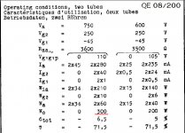
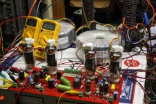
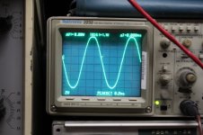
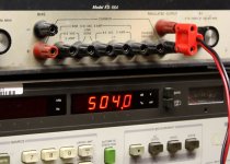
An amp that produces 500 Watts RMS for brief periods of testing (a minute or two of constant full power), but is normally used to play music (even if cranked into clipping) will require far less tubes, and iron than an amp that is required to produce 500 Watts RMS at 20 Hz continuously forever. The pictures below show 4 35LR6 TV sweep tubes cranking out 504 watts RMS at 5% distortion. This would be OK for music, but would live a short life if run like this continuously. I don't plan on continuous operation, but will use 6 tubes of this size, or possibly 4 larger tubes.
The Plitron toroidal OPT's shown in the background are rated for "400 Watts @ 20 Hz." The HF 3db point is at about 80 KHz without feedback. They are very expensive OPT's. The tubes will red plate if cranked near 500 watts at 25 KHz due to the capacitance being driven. This, again is not an issue with music, but will be a big problem for continuous duty.
An OTL configuration has been suggested, and this may be possible, but you state that you want to use "current production tubes." Most OTL's bump up against, or violate the output tube's peak cathode current rating. This may be possible with music since the peaks are seldom seen, but the amp will fail if operated contiguously at full power into the minimum specified load impedance. The tubes that I use with an OPT are rated for 1.4 amps of peak cathode current. You will need a lot more current handling capability to drive an unspecified load impedance without an OPT. I am not aware of any current production tubes with a peak current capability even near 1 amp.
It may be possible to design an amp similar to an OTL, but use a toroidal autotransformer to act as an impedance matcher in such a manner as to reduce the peak current needs, yet preserve the amp's bandwidth. I'm still not sure that you could get near 300 KHz though.
I will be using TV sweep tubes which are no longer in production, but a big bunch of KT88's could be used instead. The total number of tubes will be determined by the final application and usage constraints of the amp.
An amp that produces 500 Watts RMS for brief periods of testing (a minute or two of constant full power), but is normally used to play music (even if cranked into clipping) will require far less tubes, and iron than an amp that is required to produce 500 Watts RMS at 20 Hz continuously forever. The pictures below show 4 35LR6 TV sweep tubes cranking out 504 watts RMS at 5% distortion. This would be OK for music, but would live a short life if run like this continuously. I don't plan on continuous operation, but will use 6 tubes of this size, or possibly 4 larger tubes.
The Plitron toroidal OPT's shown in the background are rated for "400 Watts @ 20 Hz." The HF 3db point is at about 80 KHz without feedback. They are very expensive OPT's. The tubes will red plate if cranked near 500 watts at 25 KHz due to the capacitance being driven. This, again is not an issue with music, but will be a big problem for continuous duty.
An OTL configuration has been suggested, and this may be possible, but you state that you want to use "current production tubes." Most OTL's bump up against, or violate the output tube's peak cathode current rating. This may be possible with music since the peaks are seldom seen, but the amp will fail if operated contiguously at full power into the minimum specified load impedance. The tubes that I use with an OPT are rated for 1.4 amps of peak cathode current. You will need a lot more current handling capability to drive an unspecified load impedance without an OPT. I am not aware of any current production tubes with a peak current capability even near 1 amp.
It may be possible to design an amp similar to an OTL, but use a toroidal autotransformer to act as an impedance matcher in such a manner as to reduce the peak current needs, yet preserve the amp's bandwidth. I'm still not sure that you could get near 300 KHz though.
Attachments
definitely ditch the output xmfr as impractical with given frequency range, V, W
your manager really shouldn't be coy with fundamental design specs like load Z, operating requirements needed to calculate output device stress
but with the little given I'd rather start with a SiC MOSFET http://www.st.com/content/st_com/en...andgap-transistors/sic-mosfets/sct10n120.html
10 ms (longest pulse on graph) SOA only shows thermal limit
there are also 1700 V related parts from other players
Full power, 600 Watts, at 300 KHz will require better OT core material than M-6 or Hi-B. Gonna need something like ultra thin lamination nano-crystalline or amorphous core. Gonna cost big time for a core that -also- meets 600 Watts at 20 Hz. Can probably do 2:1 turns (4:1 Z) hi-BW windings as single layer winds on the big toroid core (to reduce distributed capacitance). Circlotron mode necessary to reduce the primary turns to one layer.
If not running in OTL mode (the most sensible for a 96 Ohm load), then maybe could split the HF end of the BW out as a separate amplifier using a ferrite OT core, and the LF amplifier using M-6 core etc. Then sum the LF and HF amplifier OT secondaries. The frequency crossover can be done at the amplifier inputs.
An OTL Circlotron, using TV Sweep tubes, is probably the only hope for a (one off) cheap design. Use two Industrial V change power transformers (Epay) for the floating Circlotron B+ supplies.
.
Last edited:
- Status
- Not open for further replies.
- Home
- General Interest
- Everything Else
- Design a particular push pull 600W output stage