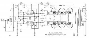
Being a doodler, I was looking for something to doodle and I found this DePalma amplifier at http://depalma.pair.com/Analog/analog.html so I doodled it up as I would choose to see it (errors notwithstanding).
Is this amplifier design worth playing with?
I've never seen an OPT that looks like that, would a UL transformer work there instead?
It's certainly more powerful than I would ever build. I assume it's fairly straight forward to eliminate a pair (at least) of output tubes(?). I don't see too many people wanting to splurge on a dozen EL34's for a stereo amplifier unless it has a pretty impressive reputation.
..Todd
Attachments
Last edited:
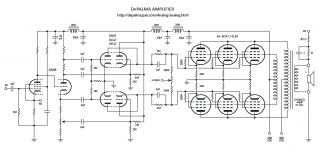
Must be some wiring errors around that 6SN7 stage(s). Not looking too sensible. Probably a differential stage, followed by a cathode follower stage, intended.
Must be some wiring errors around that 6SN7 stage(s). Not looking too sensible. Probably a differential stage, followed by a cathode follower stage, intended.
No doubt there's an error, I'll check again. Follow the link in msg #1 to the original, see if you can figure it out. Each 6sn7 is wired with their triodes in series (cascode?) from right to left. The upper and lower should be symmetrically identical.
..todd
Last edited:
I'd be hesitant to use one bias adjustment for three tubes, unless you can rely on matching sextuplets.
Not matching and using individual bias adjustments would require splitting off the coupling caps and using six of them. More complications.
800V B+ is kind of pushing the envelope.
Not matching and using individual bias adjustments would require splitting off the coupling caps and using six of them. More complications.
800V B+ is kind of pushing the envelope.
What was behind using a 3rd winding on the OPT? Does it have some advantage over using UL taps? Can a more conventional UL tapped transformer be used there?
..Todd
..Todd
If you use UL taps you are fixed at the plate voltage. If you use a separate winging for the Screen feedback you can set the screen voltage to whatever is required for tubes that require the screen to be lower than the plate.
eg, 6CA7 has a max plate of 800V and a max screen of 425V.
eg, 6CA7 has a max plate of 800V and a max screen of 425V.
Very nice drawing. What did you use for software?
Thanks. It's just drawing software (Adobe Illustrator), not a schematic CAD program. I'm an old graphics guy trying to learn amplifier electronics. Drawing the circuits out helps me learn.
..Todd
The schematic is making more sense now, but two more errors I think.
1) The 1 uF cap connections from the 6AN8 triode cathode resistors need to be swapped. With 6SN7 totem pole drivers, the bottom grounded cathode 6SN7 needs less grid drive than the top cathode follower's grid drive. The cap pickoffs for the top 6SN7s appear to be correct already.
2) Because the 6SN7 grounded cathode driver sections are inverting (left side 6SN7s), but the cathode follower sections are non-inverting (right side 6SN7s), a further swap is needed between the 6AN8 plate and cathode 1 uF cap pickoffs going to the left side 6SN7 grids. (or could swap the right side 6SN7 grids instead)( I don't see any phase dots on the OT to determine feedback phase to select between these two options.)
Last edited:
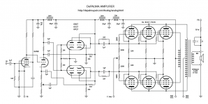
You're right. I really messed up the driver stage grids. This should fix it. (And I've fixed the transformer model number too.)
But I don't understand what you said about the OPT phase dots. How do they work? (There's none on the original schematic).
Note to self: fuel doodling sessions with coffee, not beer.
..Todd
But I don't understand what you said about the OPT phase dots. How do they work? (There's none on the original schematic).
Note to self: fuel doodling sessions with coffee, not beer.
..Todd
Attachments
Last edited:
- Status
- Not open for further replies.
- Home
- Amplifiers
- Tubes / Valves
- DePalma redux