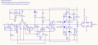
Last month had a bad fight with this amplifier. Has been in service, not repaired.After figuring out that without schematic will be shooting in the dark... also because of curiosity for their "no global feedback" design, decided to draw it off from the PCB. And there was no surprise - it have global feedback. Also distorting capacitors, wired like 69 on the input... they are there for nothing different than distortion.
Bad construction, difficult for repair - should remove front panel, knobs, input selector, power LED... after that the PCB can be slightly turned aside.
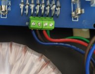
First problem - caused by previous service - was broken the power input screw terminals - the wires from transformers are single core (directly from the transformer winding) and are not flexible. It's very easy to break the terminals with them.
Second - 0,7V offset in the output. Was suspected transistor or diode... all measured good on the PCB. Started off-PCB check - gain, leakage... all OK. Moved to the other channel and others channel transistors on this - the problem remains. Checked all resistors... still not working. At that moment started to draw the schematic 😀 After all... few hours later, found that C6* is shorted and can measure 100 ohms on it
As we can see, there IS global feedback 🙂 T8-T9 what are doing there? Soft clipping, current limit, active biasing?
Bad construction, difficult for repair - should remove front panel, knobs, input selector, power LED... after that the PCB can be slightly turned aside.
First problem - caused by previous service - was broken the power input screw terminals - the wires from transformers are single core (directly from the transformer winding) and are not flexible. It's very easy to break the terminals with them.
Second - 0,7V offset in the output. Was suspected transistor or diode... all measured good on the PCB. Started off-PCB check - gain, leakage... all OK. Moved to the other channel and others channel transistors on this - the problem remains. Checked all resistors... still not working. At that moment started to draw the schematic 😀 After all... few hours later, found that C6* is shorted and can measure 100 ohms on it
As we can see, there IS global feedback 🙂 T8-T9 what are doing there? Soft clipping, current limit, active biasing?
Attachments
> T8-T9 what are doing there?
V/I limiting. Standard on most tranny amps since 1967. Here drawn a little different than usual.
Leach Amp Protection Circuit
V/I limiting. Standard on most tranny amps since 1967. Here drawn a little different than usual.
Leach Amp Protection Circuit
Attachments
C6 is not shorted, you measured R13 instead
measured desoldered from the PCB
80s axial Philips, 6,3V, a couple of transistors had been changed before me - maybe massive short and overvoltage on the cap caused the short of the cap
Hi Milen did you managed to successfully repair your DM 10?
I'm also working on a DM10 and realize it's difficult to find any schematic and service manuals on this model. Appreciate any tips and advice along the way. Thanks in advance.,
I'm also working on a DM10 and realize it's difficult to find any schematic and service manuals on this model. Appreciate any tips and advice along the way. Thanks in advance.,
Hi, I have the schema, but the value of is set to "encrypted". I made the annotations, they are the electrolytics of the power supply, at least they are the ones I changed from my amplifier. I also put instructions for DC offset adjustment.
Hope it helps
Greeting
Hope it helps
Greeting
Attachments

- Home
- Amplifiers
- Solid State
- Densen Audio DM-10 schematic