Hello,
my denon amplifier x3300 is giving -64 dc voltage at the power transistor emitter side.As per the manual I should read 0VDC.
The high dc voltage problem exist in SBL, FR, FL channels,
other channels reads milli volts
I checked and replaced the faulty power transistors in the faulty channels.
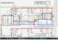
Right now I am concentrating on the FL channel. screenshots are attached.
The reading in red/blue color are as given in manual.
The reading in green are my observation.
I have replaced the darling ton power transistor pairs and Q409. Also replaced all the other transistors, but still the same problem.
Note: The amplifier board is removed from the amplifier and connected separately for troubleshooting, only DC power supply is connected and the pre input/speaker output cables are disconnected.
Please help
my denon amplifier x3300 is giving -64 dc voltage at the power transistor emitter side.As per the manual I should read 0VDC.
The high dc voltage problem exist in SBL, FR, FL channels,
other channels reads milli volts
I checked and replaced the faulty power transistors in the faulty channels.
Right now I am concentrating on the FL channel. screenshots are attached.
The reading in red/blue color are as given in manual.
The reading in green are my observation.
I have replaced the darling ton power transistor pairs and Q409. Also replaced all the other transistors, but still the same problem.
Note: The amplifier board is removed from the amplifier and connected separately for troubleshooting, only DC power supply is connected and the pre input/speaker output cables are disconnected.
Please help
Attachments
There is no current drain on Q402 or Q407. Why have you got 4volts be on Q411?
Were the components you replaced faulty ... I think probably not.
Were the components you replaced faulty ... I think probably not.
Q402 is not conducting neither is Q407.
There is 4volts b e on Q411, the maximum is around 0.6volts for silicon transistor junctions.
What have you got on Q401?
There is 4volts b e on Q411, the maximum is around 0.6volts for silicon transistor junctions.
What have you got on Q401?
Q401 has Emitter = 20v, C= -40v, B=20V.
i have marked it in the attachment.
I have tested all transistors except Q407, because it is SMT type. not easy to remove.
I test the transistors with the below procedure, pls correct if anything more required.
PNP type
put multimeter in diode mode.
when Base connected to negative terminal, collector and emitter should read around 0.5V
when Base connected to positive terminal, collector and emitter should read open circuit.
NPN type
put multi meter in diode mode.
when Base connected to positive terminal, collector and emitter should read around 0.5V
when Base connected to negative terminal, collector and emitter should read open circuit.
The voltage on Q401 is wrong.
You need to fault find the circuit now.
There must be +56volts on its base making the emitter +57 ish, (0.6volt drop).
If we consider your readings, the zener diode must be faulty or is it the +62 volt supply is wrong.
You need to fault find the circuit now.
There must be +56volts on its base making the emitter +57 ish, (0.6volt drop).
If we consider your readings, the zener diode must be faulty or is it the +62 volt supply is wrong.
Q407 can be tested in circuit as it is a dual matched transistor in a 5pin case but I doubt it is at fault.
what do you mean by the +62 power supply is wrong, I am receiving +64vdc.
please explain further.
please explain further.
Lemme chime in. Q401 has wrong voltages. Check R401 and R703. What is the voltage on their junction? Pin#2 of Q407 can never have a negative voltage on it. Maybe this transistor is bad after all.
The base of Q401 can be too low for one of two reasons, either the zener diode is open circuit or there is not full 64volt supply is not there.
With no positive drive current to the output stage, the output stage will default to -64volts.
Simple as that.
With no positive drive current to the output stage, the output stage will default to -64volts.
Simple as that.
Hi
I replaced Q407 the surface mount type and that side got cleared. Q401 and Q407 are reading correct now.
The problem shifted to Q411 collector reading 64v.
The base and emitter are reading around -60v. i tried replacing the Q411, still the same.
replaced D401, checked R403 and 405 all OK.
but Q411 collectors still reads 64V. pls advise.
Also R415/439 resistors blow off.
The emitter of Q410 reads milli volts only but the emitter of Q404 reads -66v which constitutes for the R415/439 resistors blow off.
Please advise
I would say now you have found the original fault, check replace R404/410/409/402/412 and of course the fire proof resistors R415 & 419 then apply power from a variac monitoring what is wrong as you increase the HTs with care!
Hi,
checked the below components, found no problems.
R404 is not used in the circuit, open
R410 is a wire jumper not a resistor
R409 measures 148kohm which matches the specs/manual
R402 measures 100k which matches the specs/manual
R412 measures 47kohmwhich matches the specs/manual
any other suggestions.
Also please let me know of any known websites to purchase the HN4A06J - Silicon PNP Epitaxial Type (SOT-153) and fire proof resistors in Uk/USA. these are locally available in my location. I have to ship from some where else.
Many thanks for the support and advises.
Check all the voltages on the parts of the circuit between Q402's collector and the output node, something is open-circuit along there. What's the voltages on all 3 pins of the bias transistor Q409?
Hi i checked the voltages
Q409 Emitter -67v , collector -67v, base -57v ( i already replaced it)
Q402 Emitter 68v , collector -67v, base 67.5v ( i already replaced it)
Q412 Emitter -67.4v , collector -67.4v, base -63.3v ( i already replaced it)
R432 measures -67.3v
Q409 Emitter -67v , collector -67v, base -57v ( i already replaced it)
Q402 Emitter 68v , collector -67v, base 67.5v ( i already replaced it)
Q412 Emitter -67.4v , collector -67.4v, base -63.3v ( i already replaced it)
R432 measures -67.3v
- Home
- Amplifiers
- Solid State
- Denon x3300w amplifier speaker output giving high dc voltage