Hello everyone,
As this is my first post, I'd like to thank the members of this forum for solving a lot of questions I had before - there seems to be a lot of knowledge here, so here's my "problem":
The noise floor on my Denon PMA 900V is a bit high for my taste and seeing that I can only twist the volume knob for about 20° before my neighbors are complaining and never turned it over 9 o'clock until it was "loud enough", I'd like to lower it's gain and/or swap the opamps for less noise.
It's service manual can be found here, the opamps used are Mitsubishi M5218 for IC1, 5, 7 & 8 (datasheet here) and a Sanyo LA6458 for IC2 (datasheet here) in the Phono-Pre section.
All opamps are dual versions, but I'm not shure wether they are J-FET or bi-polar types (or wether they are used for current or voltage feedback in the circuits).
Any suggestions on what opamps to swap in and/or how to lower the overall gain (or noise) of the circuit to optimize it for modern day >1.5V rms sources?
I thought it would be a good idea to come and ask here before the monkey in me takes over and I put LME49720s with a ceramic caps between pins 4+8 everywhere 🙄 ...
Nobody here able to help
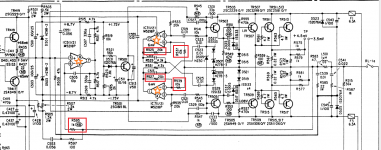
I shall try to ask again - this time focusing only on the bias and feedback circuit of the amp. Attatched is a picture of one channel with the ICs and resistors I'd like to change (at least from current carbon to metal-film types). Marked red are the negative feedback resistors and marked with orange stars are the opas. If my (very limited) understanding serves my right, IC5 is for the bias and doesn't have that much influence on the sound and noise compared to IC7.
Is there any benefit in further changing, say R533/R535, R541/R543 to metal film type in terms of noise and/or sonics?
Is there anything else I could optimize here to make an LM4562/LME49720 "more comfortable" or, in the best case, lower the gain?
Attachments
It is clear that you have no understanding of the circuit at all hence you should not meddle with it. Neither of the components you reference has any bearing on the gain of tha amplifier, the circuit is a form of error correction acting only on the output stage which as NO voltage gain. Operational amps are universal components, so why assume they have anything to do with amplification directly? Meddling with said components ratios or using an OPamp which might not be suited will result in an output stage nicely burnt to crispy black, with matching crates in your output transistors.
I see that you have the service manual, see if you can identify which part of the circuit actually is responsible for amplification, that would be a good start.
I see that you have the service manual, see if you can identify which part of the circuit actually is responsible for amplification, that would be a good start.
Last edited:
The components with NB circled around them are safety components and must not be changed unless with the same type and value.
Please learn the basics before changing random components.
Please learn the basics before changing random components.
Thanks for the warning. I'll try to stick to upgrades to the power supply, then.
I wasn't going to change the value of any of the marked resistors - but what danger is there changing from 1/4W carbon type to .4-.6W metal film type (other than not making a proper connection 🙄) as long as they fit? Aren't metal film types "more safe" (when marketed as flame resistant) and stable?
On another end: the headphone outs are provided by 120 ohms mox type resistors at the output. It's terribly noisy and doesn't sound good. Any remedy here short of highjacking the input and putting a dedicated amp here?
I know that I don't know much, if anything useful, about circuits. But "when you only have a hammer, everything looks like a nail". I'll try to get hold of books on amplification. Maybe that could help taming my inner Jeremy Clarkson.
The specs do not suggest an unusually noisy amplifier, but those may be referring to operation with the tone controls turned OFF. So I suggest doing this (preferably flip the switch back and forth a few times, it may not have been used in quite a while) and reporting back on whether that helped.
This amplifier has a "processor loop" feature which could be used to include an attenuator of about -12 dB, which would then be effective for all sources. If there is only one source, I'd just put it inline at the input.
Modifying power amp gain is always a bit tricky because you usually need to adapt compensation. This one also has its tone controls in the feedback, which doesn't make things any easier.
EDIT:
120 ohms of series resistance for the headphone out does in fact seem a bit low when coming from a power amp's output. This amp is rated at 120 W / 8R, that's 31 Vrms. There is little attenuation until we get into the medium impedance range, so it's little wonder the headphone output is noisy. (There should be at least 12-20 dB of attenuation for any type of headphone.) I would suggest turning the whole shebang into an L-pad using 2 resistors per channel (1 series, 1 in parallel), but in order to optimize the values, you'd have to tell us what exact model headphones you have. There's always a tradeoff between output impedance and maximum level.
Last edited:
I am almost exclusively using the amp in processor loop mode. Phono input, however, only works through the processor. There is very little audible difference between switching the tone controls on or off - they're off, all the time. I also make shure to use every switch and knob there is from time to time, so everything is working fine.
There is a -20db muting feature built-in - somehow I find that it dulls the sound a little, although I'm not shure that's because testing it involves adjusting levels all the time or because my brain is playing tricks with me. However, using it enables me to run full 2V rms at the input without having only about 10° of volume knob adjustment between barely audible and neighbors complaining. There's no need for any external attenuation.
Yes, the specs don't say that this amp is noisy. The headphone outs say otherwise. Any noise produced by the amp at the speakers becomes inaudible at acound 60cm away from the tweeters/mid-domes. 20cm would be nice...
There are some "funny" things going on the pcb - e.g the processor gets it's power via a blob of solder that shorts two pcb traces and the main ground traces going from the psu-ground to the main transistors were about 1mm wide. The latter caused them to literally burn up. There are also some traces not propperly printed and some cold solder joints I fixed.
Great Idea with the L-pad, sgrossklass! You're right, it's downright inbearable with 16 ohm IEs and only terrible with 70 ohms and up. I'm mainly using Sennheiser HD-25s in 70 ohm. Specsheet says 200mW are fine (for the headphones, that is...I'm quite shure I'll never listen that loud). What value of resistors should give 15-20dB of attenuation, here?
"Regular speaker" L-pad calculators want me to use 100W capable resistors (for the serial resistor) with about 63ohms series and 7.8 ohms parallel resistance for 20dB of attenuation instead of the 1W-things currently in use 😱 . Is that really neccecary in practice? I'd rather blow a resistor instead of headphones...
Sorry for double-posting, editing seems to be disabled for every post except the first one and every post seems to need approval of a mod before showing up. Not shure if a monkey on a leash is better than one without one, here...
I just realized that an L-pad would have a resistor that permanently parallels the speaker outs. That's not acceptable. It would need a switch of some kind to not do that. Suddenly it gets much more complicated...I'd rather not put in extra relais/manual switches for this purpose...
Going back to the original series-only design (and quickly discarding any thoughts about transformers...), are metal-film type resistors of the same (or different) value less noisy?
This "every post has to be confirmed by a moderator, first"-business without beeing able to edit is really starting to go on my nerves. Mod reading this, am I really that offensive/dangerous/stupid? I promise not to sue, should I manage to blow the main psu caps in my face and take out every device attatched to whatever is on the same fuse.
This "every post has to be confirmed by a moderator, first"-business without beeing able to edit is really starting to go on my nerves. Mod reading this, am I really that offensive/dangerous/stupid? I promise not to sue, should I manage to blow the main psu caps in my face and take out every device attatched to whatever is on the same fuse.

Its not every post. It is until we feel individual members can be trusted and then your posts will slip from moderation. It is a system that works well.
From what you've posted, it sounds like you may be running a line level source into the phono input? If so, therein lies your problem.
Mike
Mike
That's a good one 😀From what you've posted, it sounds like you may be running a line level source into the phono input? If so, therein lies your problem.
Mike
A friend of mine actually did this once and couldn't figure out why the sound was so bad...took me about 10 seconds to find and fix the problem...
I might be stupid, but I'm not that stupid.
The amp sounds fine as is, google will tell you the same. But it could always be better... Reading around here and comparing specs I had the idea of an opa-roll and changing the feedback resistors from carbon to metal film-types, but it seems that that's discouraged. I've given up on any kind of gain-modifications at the actual amp, since it's waaaay above my understanding of circuits.
Now the only "real problem" the amp has is excessive noise when the headphone out is used (for headphones, of course). The main speakers aren't anywhere near as noisy and I suspect that that not only has to do with the sensitivity of headphones but also with the 120 ohm resistors that are in series to the main outs, providing the headphone out.
The idea of switching from a series resistor to an L-pad voltage divider feels worrysome, since the L-pad would also be permanently in use when regular speakers are used (there is no switch or relay for the headphones, only for the speakers). But I could build an L-pad and connect it to the 2nd pair of speaker outs (wich have a switch and are never used) and use them to power headphones.
According to a calculator and my head, the current 120ohm resistor makes for around 6 dB of attenuation - clearly not enough to get an exceptable noise floor.
I tried playing around with this calculator and 6 ohm series as well as 1 ohm parallel resitance would net an attenuation of 17dB as well as an effective headphone output impedance of 0.86 ohms at a speaker load to the amp of 7 ohms. That does sound good on paper - would that work in practice?
HD25s still are very easy to drive and will go plenty loud on most any portable source, so I'm not surprised. 48 mV for 90 dB SPL... I don't think you'll need more than half a volt there, similarly for in-ears. I'd try 330 ohms (5 W) in series (replacing the 120Rs) and 5.6-10 ohms (1/4 W) in parallel to the output. That should bring your levels down by >20 dB from where they are now, while providing lowish output impedance. Maximum power dissipation would be <3 W, and I suppose you're not usually cranking levels to max.Great Idea with the L-pad, sgrossklass! You're right, it's downright inbearable with 16 ohm IEs and only terrible with 70 ohms and up. I'm mainly using Sennheiser HD-25s in 70 ohm.
I'm not sure what the headphone output would have been suitable for, stock. It's plenty hot even for K340s or K240DFs. Definitely way too much so for anything that's not notoriously insensitive.
I shall try to ask again - this time focusing only on the bias and feedback circuit of the amp. Attatched is a picture of one channel with the ICs and resistors I'd like to change (at least from current carbon to metal-film types). Marked red are the negative feedback resistors and marked with orange stars are the opas. If my (very limited) understanding serves my right, IC5 is for the bias and doesn't have that much influence on the sound and noise compared to IC7.
Is there any benefit in further changing, say R533/R535, R541/R543 to metal film type in terms of noise and/or sonics?
Is there anything else I could optimize here to make an LM4562/LME49720 "more comfortable" or, in the best case, lower the gain?
I don't understand the theory of operation of this power amp circuit - especially those of the OP-Amps.
There is a certain similarity to Electrocompaniet's Ampliwire AW-100 go to post #3 (first PDF file) under
Electrocompaniet Ampliwire 100 (AW 100 AW100) different Versions
But what are the aim of the operational amplifiers IC511 and both halves of IC711 in detail (go to the attachment in post #2) ?
Are this an invention from DENON or is there a well-known naming for this topology (maybe a kind of error correction) ?
Thank you very much for some advices.
Last edited:
Denon's PMA700V use basically the same topology - go to
about the Denon PMA-700 amp
for some circuit descriptions in post #17-19.
about the Denon PMA-700 amp
for some circuit descriptions in post #17-19.
- Home
- Amplifiers
- Solid State
- Denon PMA-900V lowering gain/opamp swap