Iv lifted this description of the issue from another post as I cant put it any more succinctly myself.
Basically iv tried contact cleaner into the pot with no success. I'm wondering weather it would be worth de-soldering the pot from the board and attempting to service it? If so how would I do this?
If its not serviceable could I replace the pot with a new one? If so how would I find out which type to buy? Iv seen replacement pot's in values from 1k ohm to 1m ohm, and linear mono, linear stereo, logarithmic mono, etc. I know absolutely nothing about electronics so these values unfortunately mean very little to me.
The pot is quite easy to access to I have no issues with de soldering it from the board.
Any help would be greatly appreciated. Cheers.
Denon PMA-250 amplifier -Volume knob not responding correctly, high volume on low setting, sometimes crackly and sometimes only works through one speaker, can improve by manipulating the knob.
Basically iv tried contact cleaner into the pot with no success. I'm wondering weather it would be worth de-soldering the pot from the board and attempting to service it? If so how would I do this?
If its not serviceable could I replace the pot with a new one? If so how would I find out which type to buy? Iv seen replacement pot's in values from 1k ohm to 1m ohm, and linear mono, linear stereo, logarithmic mono, etc. I know absolutely nothing about electronics so these values unfortunately mean very little to me.
The pot is quite easy to access to I have no issues with de soldering it from the board.
Any help would be greatly appreciated. Cheers.
Just looking at pots and most seem to have 3 pins or 2 rows of 4. The one Im looking to repair/replace has 6 pins. Perhaps Im searching for the wrong thing?
Anyone?? I just want to know how to go about finding a suitable replacement pot if they can't be repaired.
Have you resoldered the pot ?....the symptoms describe intermittent earth connection.
I have repaired pots in the past by dismantling them and squashing the pins that connect to the track pcbs with pliers...restore the compression connection.
Silver conductive paint may be needed also...at the pins.
Dan.
I have repaired pots in the past by dismantling them and squashing the pins that connect to the track pcbs with pliers...restore the compression connection.
Silver conductive paint may be needed also...at the pins.
Dan.
Last edited:
Hi,
I'll try to help you, but I'm afraid that it could be a long explanation, based on the questions you ask...
The symptoms are probably from a faulty potentiometer indeed, and it is indeed easy to replace, all you need is a close enough value, and a geometry that fits in the mounting of the current one.
The potentiometers are marked most of the time.
Can you spell us, or take a picture of the markings on yours, then we can tell you what it is.
There's tons of info about this on the web.
For example here: Potentiometers (Beginners' Guide to Pots)
Cheers,
g.
_
...well...
when I said they're marked "most of the time"...
this is a case where I can't really make sense of the numbers...
However:
- There may be other numbers on the side of the pot (although it looks skinny)
- You can always measure it with an ohm-meter (why didn't I think of this before...) This is easier to do If you get it out of the board, but you can make a good guess even when mounted.
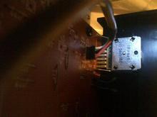
As you see, there are six pins, which makes two potentiometers, one per stereo channel. (Some pots that are less easy to replace would have an additional pin per channel, used for "loudness control"...)
The shape of this pot is not the most common to buy as a spare.
You could also get one with different pinout, that fits in the front panel hole and then connect it to the board with short cables. This then depends on what you can fit on the front side...
As I said, all this is a bit long to explain in full detail...
And as it was suggested, you should try to check the soldering of the six contacts on the PCB before going for a replacement. Why don't you resolder them anyhow: it won't hurt and it may solve things.
_
when I said they're marked "most of the time"...
this is a case where I can't really make sense of the numbers...
However:
- There may be other numbers on the side of the pot (although it looks skinny)
- You can always measure it with an ohm-meter (why didn't I think of this before...) This is easier to do If you get it out of the board, but you can make a good guess even when mounted.
As you see, there are six pins, which makes two potentiometers, one per stereo channel. (Some pots that are less easy to replace would have an additional pin per channel, used for "loudness control"...)
The shape of this pot is not the most common to buy as a spare.
You could also get one with different pinout, that fits in the front panel hole and then connect it to the board with short cables. This then depends on what you can fit on the front side...
As I said, all this is a bit long to explain in full detail...
And as it was suggested, you should try to check the soldering of the six contacts on the PCB before going for a replacement. Why don't you resolder them anyhow: it won't hurt and it may solve things.
_
Last edited:
That style of pot has a plastic disc shaped end to the shaft that holds two wiper contacts via small peened over rivets.
These rivets break and the contacts are then loose causing connection issues.
If you are really good you can dismantle the pot and repair the contacts mountings.
Easier is to replace with a standard log pot and run connecting wires.
Dan.
These rivets break and the contacts are then loose causing connection issues.
If you are really good you can dismantle the pot and repair the contacts mountings.
Easier is to replace with a standard log pot and run connecting wires.
Dan.
Agreed, I had a JVC pro. amp with a similar pattern pot. - an absolute sod to dismantle and repair. There seems
to be plenty of room around the pot. and since there is no loudness tapping apparently, you could fit a standard
ALPS RK27 type of the correct audio taper (log) and value according to the label.
Just wrap the pins with solid core hook-up wire and fit to the relevant PCB holes. Unless you have schematic,
you will need to be certain of what channel and which connection, either start, end or wiper it is you are
dealing with by simple, logical checks with a multimeter on the original pot. Use a suitable resistance range to
encompass the value of the pot. Just remember; you'll be looking at transposed start/ends from the rear and
you need adequate shaft length and the right splined or plain shaft.
Of course, you can fit any old brand log pot. of any quality and it will work OK but I guess you will want to lavish
top quality parts on it and the 8 quid or so +post on Epay might be only a small price?
Last edited:
Thanks a lot for the reply's. Unfortunately I have never used a multi meter (I do own one Iv never used) and m knowledge of electronics is virtually non.
I like the idea of just buying a replacement pot rather than repair. My skills are only really basic soldering so using a pot with different pin outs and finding where to solder the leads using even basic principles would be tough for me.
The amp cost e nothing and would other wise of been binned so it owes me nothing. As long as it works it would be a bonus really. Im not too bothered about what parts I use to fix it. It will just be a spare amp really.
Shame for it to go to land fill tho :/
it is NEVER to late to learn how to use a multimeter!!! you are in DiyAudio and can get ALL the help that you want to fix you amp. since you want to put this amp in the garbage...Why don't you "practice" with it and try to replace that potentiometer. There are a lot of videos on the web showing how to use a multimeter and how to solder.😉
https://www.google.com.au/search?q=...e=univ&ei=r39dUZ7AJszyrQfB9oCgBA&ved=0CDYQsAQ
Here, there should be a little inspiration in these pics and really, identifyingn 2 separate potentiometers and which end is ground or signal is not rocket science and the variable signal out terminal is the remaining terminal by default. The value of the resistances is marked on the pot and all you have to do is select a resistance range (make sure the battery is in the meter) that covers this value and look under the PCB for the earth or grounded connections which will likely be joined at the PCB trace and that gives you 2 down to start with and the rest follow logically by verifying the resistance you read does not vary with the shaft rotation for the input end and does vary for the wiper (output). The actual value is not greatly important and the pics will help with some of the simple reasoning involved.
I think it's obvious that to measure resistance between 2 points, you place a probe on each with the leads in the appropriate sockets and appropriate range selected on your meter - thats one that gives a meaningful , not over or underrange reading but perhaps according to what you expect.
Last edited:
it is NEVER to late to learn how to use a multimeter!!! you are in DiyAudio and can get ALL the help that you want to fix you amp. since you want to put this amp in the garbage...Why don't you "practice" with it and try to replace that potentiometer. There are a lot of videos on the web showing how to use a multimeter and how to solder.😉
I said already Im fairly competent at soldering and would happily attempt to replace the pot. I am trying to prevent this from becoming "garbage". Binning it is the opposite of what I want to do.....
I don't know any electronics theory so I would not know where to start with a multi meter. all the hep iv had so far has unfortunately been a little bit to technical but I appreciate the help all the same!
I had hoped that it would be a case of sourcing a replacement and that I could e able to get help in locating this. I dont have the time to learn electonic theory just to fix an amp....I wish I did, I really do 🙁
If you want to have a go at fixing it then something like this should work... I haven't looked at the manual for the value fitted... this is just to show you the sort of thing you would fitting.
Maplin code FX11M The link probably won't reference the exact part.
Standard Dual-Gang Potentiometers : Potentiometers : Maplin Electronics
Maplin code FX11M The link probably won't reference the exact part.
Standard Dual-Gang Potentiometers : Potentiometers : Maplin Electronics
Yesterday I replaced the broken pot with another one with a similar layout which I found on ebay for about £5. It works! The new pot was a lot smaller, so I couldn't just solder it straight to the board as the shaft would have been in the wrong position. Luckily the hole in the front plate was the exact correct size to fit the new pot into. I found a flat nut to keep it in place and then soldered some wires to the legs and then soldered them to the board instead.
Only problem now is that the volume nob wont fit onto the new pot's shaft as its thinner. So I need to come up with something to attach it. But I'm quite pleased with it!
Only problem now is that the volume nob wont fit onto the new pot's shaft as its thinner. So I need to come up with something to attach it. But I'm quite pleased with it!
That was all a while ago ! If the shaft is thinner then you could try wrapping with something or even a tiny dab of epoxy. If it the other way around the hole in the knob is to small then options are limited. You could try removing the central part and using epoxy or body filler.
Be careful with any epoxies... its easy to end up with it on the pot shaft where it exits the pot body.
Be careful with any epoxies... its easy to end up with it on the pot shaft where it exits the pot body.
- Status
- Not open for further replies.
- Home
- Amplifiers
- Solid State
- Denon PMA-250 amplifier - volume issue