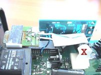
Hi, does someone know the parts to remove on the board to mount a new clock ( the Burson audio one) ? Thanks .
Locate (and confirm) that IC104 is Yamaha receiver YM3623B.
Remove C428, C429, R415 and X101 (16.934MHz). Feed the oscillator clock signal in to IC104 pin 6. Connect the oscillator ground to lowest noise section/area of the ground plane around receiver chip you can find. Use external power supply with the lowest amount of noise you can obtain.
Good luck,
Boky
Extreme_Boky said:Locate (and confirm) that IC104 is Yamaha receiver YM3623B.
Remove C428, C429, R415 and X101 (16.934MHz). Feed the oscillator clock signal in to IC104 pin 6. Connect the oscillator ground to lowest noise section/area of the ground plane around receiver chip you can find. Use external power supply with the lowest amount of noise you can obtain.
Good luck,
Boky
Interesting. Presumably you have tried this mod before. Would you say it yielded much of an improvement ?
I would say the improvement was easily noticeable - however the whole clock oscillator upgrade really started to show what it was capable of after I lowered the PS noise and picked the lowest noise ground point on the PCB.
There's another xtal in this player - 15MHz, which requires exactly the same treatment as the above mentioned 16.934 xtal.
There's another xtal in this player - 15MHz, which requires exactly the same treatment as the above mentioned 16.934 xtal.
If I remember...Jocko mentioned that the Yamaha-chip only needed the clock to start/lock, and should thereafter be shut off...
And as a consequence, the clock-quality should not matter much???
I did not search, but I think there is a clock-mute-suggestion somwhere here...
Arne K
And as a consequence, the clock-quality should not matter much???
I did not search, but I think there is a clock-mute-suggestion somwhere here...
Arne K
Extreme_Boky said:I would say the improvement was easily noticeable - however the whole clock oscillator upgrade really started to show what it was capable of after I lowered the PS noise and picked the lowest noise ground point on the PCB.
There's another xtal in this player - 15MHz, which requires exactly the same treatment as the above mentioned 16.934 xtal.
Well, I am frankly amazed at the idea that anything attached to pin 6 of the YM3623B can make a difference. Not only does that crystal only work to provide a guide frequency, it only does it when the YM3623B is out of lock, ie. no spdif input. More to the point the YM3623B plays no part during CD replay.
JLPAS said:
Hi, does someone know the parts to remove on the board to mount a new clock ( the Burson audio one) ? Thanks
First you need to locate the CD processing chip and the digital filter, the CXD2515Q and the SM5845, assuming, that is, the S10 II is similar to the S10.
The oscillator at pin 62 of the CXD2515Q should be replaced with the 384Fs Burson clock. A further improvement would to replace the 384Fs feed from the CXD2515Q to the SM5845 with a direct feed from the Burson clock. To do this and still retain the SPDIF input, disconnect the C16M feed from pin 69 of the CXD2515Q and connect a second feed from the 384Fs clock to pin 14 of the 74HC157. In the S10 the correct 74HC157 is IC110. With the S10 II it would be wise to confirm pin 69 of the CXD2515Q is connected to pin 14 of the 74HC157 before disconnecting the two.
Hi rfbrw,
I mentioned the second xtal as equally important (X200) and referred to it as 15MHz (where I should’ve typed 16MHz, hhhmmmm). The actual value is 16.9344MHz. So, you followed the tip-off… good!
I replaced the Yamaha receiver chip xtal on pin 6 probably 3 times so far…. The biggest improvement I have obtained was with DPA DAC… (or something like that…) – I think DAC 7 chipset…In my personal opinion the xtal replacement was worthwhile exercise… maybe the cleaner clock and lower level of induced noise helped here…It would be interesting to see internal block diagram of YM chip.
Boky
Extreme_Boky said:Hi rfbrw,
I mentioned the second xtal as equally important (X200) and referred to it as 15MHz (where I should’ve typed 16MHz, hhhmmmm). The actual value is 16.9344MHz. So, you followed the tip-off… good!
It is actually marked as 15MHz in the manual. The YM3623B xtal is 1MHz.
I replaced the Yamaha receiver chip xtal on pin 6 probably 3 times so far…. The biggest improvement I have obtained was with DPA DAC… (or something like that…) – I think DAC 7 chipset…In my personal opinion the xtal replacement was worthwhile exercise… maybe the cleaner clock and lower level of induced noise helped here…It would be interesting to see internal block diagram of YM chip.
Boky
The datasheet tells all.
I see your point and thanks for the link. I have followed Jocko’s suggestions many times (in particular regarding SPDIF signal conditioning) with great results and I believe it is our great loss not to have his input on these forums any more.
As for “to replace or not to replace Xtal” on Yamaha receiver, pin 6, with clock oscillator, all I can tell you is that my experience was positive. DPA DAC mod yielded excellent results in fact…
It would be really interesting if anyone can post YM chip block diagram…
Boky
As for “to replace or not to replace Xtal” on Yamaha receiver, pin 6, with clock oscillator, all I can tell you is that my experience was positive. DPA DAC mod yielded excellent results in fact…
It would be really interesting if anyone can post YM chip block diagram…
Boky
Attachments
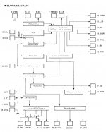
Thanks for the block diagram.
The xtal replacement on pin 6 of Yamaha receiver will not make much difference if the CD player is used only to play CD’s. It will make difference and improve sound if this CD player is used as a DAC only box. Since the thread originator hasn’t responded to my first suggestion nor commented on his intention as to what he want’s to do with this machine, I reserved the right not to comment further possible improvements…
Boky
Extreme_Boky said:T. It will make difference and improve sound if this CD player is used as a DAC only box.
Boky
How?
the same way the X200 replacement with high quality oscillator / dedicated power supply would improve jitter performance at pins 2, 5, 11 and 14 of IC110 of CD replay
From your comments it seems that you think you might know / see something I can't.... I
From your comments it seems that you think you might know / see something I can't.... I
Extreme_Boky said:the same way the X200 replacement with high quality oscillator / dedicated power supply would improve jitter performance at pins 2, 5, 11 and 14 of IC110 of CD replay
From your comments it seems that you think you might know / see something I can't.... I
It seems I do. When there is a SPDIF signal present and the PLL has locked the oscillator at pin6 is no longer used. Under those circumstances, I do not see how an oscillator that is not in use can possibly improve anything.
No you don’t.
Your whish to prove that you know and understand electronics better than me has blinded you completely. The low noise clock signal at pin 6 is ALWAYS present at internal “clock selection” block of this receiver chip, via internal oscillator,constantly influencing its performance – even if the VCO takes over. Further to this fact, what would happen if the lock is lost OR replay error occurs? What if the SPDIF signal quality is less than perfect?
You where aware of Yamaha receiver block diagram BEFORE me and instead of telling me that/ posting the block diagram straight away, you made wise remarks and comments trying to prove that you understand electronics better then I do.
I was not aware of YM chip internal block diagram and existence of VCO. This is why I asked twice in this thread if someone could post its block diagram. You could’ve posted it, or mentioned VCO straight away and pointed to its existence and possibility that it can generate clock signal - instead of trying to be smart by asking me about the benefits I obtained by replacing xtal with clock oscillator, and latter trying to prove (to yourself?) that you know / understand electronics better than I do.
Let’s talk about sound benefits, which is what all this is really about in this thread. I KNOW FOR SURE that low amount of noise present at pin 6 would ALWAYS yield much better performance EVEN when (if) VCO is generating clock signal. External clock with dedicated low noise power supply will always produce this result even if it’s needed sporadically from time to time, because it is ALWAYS PRESENT WITHIN THIS CHIP.
As to what generates the clock signal…. I would like someone who has this player to feed in SPDIF and to remove the clock signal from pin 6 when the stable lock is obtained – and we’ll see… if the CD player will continue with its duties of D to A conversion okay or not…
The whole issue and you trying to prove something here is ridicules – the YM receiver chip CAN NOT work without clock signal present at pin 6. It is questionable under what conditions, how often and for how long the internal VCO is active. So we DO need external clock source. If this is the fact and the case, why not improve the quality and lower the noise around this chip to obtain good audio quality by installing external clock oscillator anyway? The D to A won’t work without this signal on pin6.
From my experience with this chip I know that high quality clock signal at pin 6 makes big difference. The block diagram states that VCO can take over if two conditions are met AT THE SAME TIME, which is unlikely to happen for sufficiently long periods of time to justify not going ahead and replacing xtal with high quality clock oscillator to obtain low noise and good jitter performance overall.
Extreme_Boky said:No you don’t.
Your whish to prove that you know and understand electronics better than me has blinded you completely.
Oddly enough, I have never felt the need to question your knowledge of electronics.
No, what I was seeking to point out is the Emperors new clothes aspect of a lot audiophile tomfoolery. Here you are waxing lyrical
about an oscillator that isn't even in use when the audio is playing.
The low noise clock signal at pin 6 is ALWAYS present at internal “clock selection” block of this receiver chip, viainternaloscillator,constantly influencing its performance – even if the VCO takes over. Further to this fact, what would happen if the lock is lost OR replay error occurs? What if the SPDIF signal quality is less than perfect?
Of course, it is always present, if you connect it to pin 6 but the minute the PLL locks it is no longer needed. Worse still it is asynchronous with respect to the SPDIF derived 384Fs clock hence the circuit to shut it down when the PLL locks. The way the S10 is designed the xtal operates under two conditions. When the is no input or when there is PLL lock but invalid data.
You where aware of Yamaha receiver block diagram BEFORE me and instead of telling me that/ posting the block diagram straight away, you made wise remarks and comments trying to prove that you understand electronics better then I do.
Sure I was having fun at your expense but it had nothing to do with your knowledge of electronics. I was mocking all that audiophile voodoo and certainty that you seem so fond of.
I was not aware of YM chip internal block diagram and existence of VCO. This is why I asked twice in this thread if someone could post its block diagram. You could’ve posted it, or mentioned VCO straight away and pointed to its existence and possibility that it can generate clock signal - instead of trying to be smart by asking me about the benefits I obtained by replacing xtal with clock oscillator, and latter trying to prove (to yourself?) that you know / understand electronics better than I do.
Ah the the true audiophile, never one to let ignorance of the facts get in the way. If you know so little about the chip in question perhaps you should not be dispensing advice.
Let’s talk about sound benefits, which is what all this is really about in this thread. I KNOW FOR SURE that low amount of noise present at pin 6 would ALWAYS yield much better performance EVEN when (if) VCO is generating clock signal. External clock with dedicated low noise power supply will always produce this result even if it’s needed sporadically from time to time, because it is ALWAYS PRESENT WITHIN THIS CHIP.
Given the way every YM3623B I have ever seen has been connected, if the PLL is not locked, there is no audio. This is the only time the oscillator kicks in. If you are hearing the oscillator then you are listening to the golden sound of silence.
As to what generates the clock signal….
The YM3623B has two clock modes. A 384Fs clock is derived from the SPDIF datastream and the clock on pin 6 kicks when the SPDIF input is lost and a second mode in which the clock on pin6 is connected permanently irrespective of the SPDIF input. This mode may allow the YM3623B to be used with an external reference of the sort one would find in a studio but I wouldn't stake my neck on that, best test it first. Every YM3623B based device I have seen uses the first mode.
I would like someone who has this player to feed in SPDIF and to remove the clock signal from pin 6 when the stable lock is obtained – and we’ll see… if the CD player will continue with its duties of D to A conversion okay or not…
The thread linked to by Cobra2 pretty much covers that topic but I do have two '3623 equipped dacs
The whole issue and you trying to prove something here is ridicules – the YM receiver chip CAN NOT work without clock signal present at pin 6. It is questionable under what conditions, how often and for how long the internal VCO is active. So we DO need external clock source.
If this is the fact and the case, why not improve the quality and lower the noise around this chip to obtain good audio quality by installing external clock oscillator anyway? The D to A won’t work without this signal on pin6.
Because it is a total waste of time and money and in the words of the banned one . . . .
From my experience with this chip I know that high quality clock signal at pin 6 makes big difference. The block diagram states that VCO can take over if two conditions are met AT THE SAME TIME, which is unlikely to happen for sufficiently long periods of time to justify not going ahead and replacing xtal with high quality clock oscillator to obtain low noise and good jitter performance overall.
Still haven't read the datasheet I see.
There are two ways to improve the the clock of the YM3623B and your way is not one of them.
Edit. Dug out data sheet. Second clock mode is a no go for clock improvement. To quote the datasheet on Crystal mode " Signals transmitted from output terminals have no significance".
is the oscillator really stopped when there is a lock condition, or is it merely not used to clock the outputs? that would make a difference.. somehow I doubt it is stopped.. someone should check what's going on at the XTO pin when it's locked to valid S/PDIF input..
Sure I was having fun at your expense but it had nothing to do with your knowledge of electronics. I was mocking all that audiophile voodoo and certainty that you seem so fond of.
Even if I'd known of a block diagram, I would've still suggested clock mod because it works. I'll repeat myself: The external clock and its low noise clock signal at pin 6 is ALWAYS present at internal “clock selection” block of this receiver chip, via internal oscillator, constantly influencing its performance – even if / when the VCO takes over. This is what I see from the block diagram.
My experience tells me that the mod is worthwhile. There's no uncertainty about this. I have checked my backup and reminded myself of Audio Note DAC 3 which I modified the same way - it produced great results; same YM chip with XO2 clock and dedicated low noise power supply.
We have different approaches and strive different end results.
I find your ways of having fun at other's people expense rude and sick.
Boky
- Status
- Not open for further replies.
- Home
- Source & Line
- Digital Source
- Denon DCD-S 10 II clock