Hi,
I have a Denon AVC-A1SR (AVR-5803 in some areas) that exhibits quite a big DC offset at the speaker terminals (around 140mV). All channels behave in the same way.
The previous owner told me that the received experienced a power cut while on. It went straight to protection after the power was back.
I replaced all the 78xx regulators (I read that they tend to go bad in Denon receivers and I have tons of them).
Now, it powers on correctly.
What I checked so far:
- Bias currents are as specified (3mV at the test points according to the manual)
- At the input of the amps, after C129, I have 0.1mV of DC offset. Looks OK.
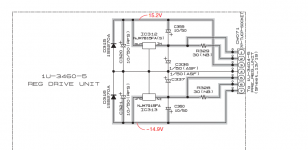
- I measured the -14.9V rail at -15.2V and the +15.2V at +15.0V (I attached the regs schematics). Is this a significant difference?
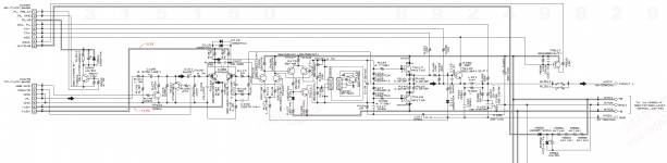
- Nothing seem obviously wrong in the amp section, no shorted transistor or diodes as far as I can tell. I guess it will be needed, so I attached the schematics for one channel (they are all identical anyway).
As all the channels in the receiver exhibit roughly the same DC offset, could it be that the amp sections are OK and somehow, the offset could come from the power supply? Or maybe they all blew up at the same time 😱...
I am used to fix amplifiers, but this one is much more complicated than what I am used to see...
Any help would be much appreciated 🙂
I have a Denon AVC-A1SR (AVR-5803 in some areas) that exhibits quite a big DC offset at the speaker terminals (around 140mV). All channels behave in the same way.
The previous owner told me that the received experienced a power cut while on. It went straight to protection after the power was back.
I replaced all the 78xx regulators (I read that they tend to go bad in Denon receivers and I have tons of them).
Now, it powers on correctly.
What I checked so far:
- Bias currents are as specified (3mV at the test points according to the manual)
- At the input of the amps, after C129, I have 0.1mV of DC offset. Looks OK.
- I measured the -14.9V rail at -15.2V and the +15.2V at +15.0V (I attached the regs schematics). Is this a significant difference?
- Nothing seem obviously wrong in the amp section, no shorted transistor or diodes as far as I can tell. I guess it will be needed, so I attached the schematics for one channel (they are all identical anyway).
As all the channels in the receiver exhibit roughly the same DC offset, could it be that the amp sections are OK and somehow, the offset could come from the power supply? Or maybe they all blew up at the same time 😱...
I am used to fix amplifiers, but this one is much more complicated than what I am used to see...
Any help would be much appreciated 🙂
Attachments
Have you checked the voltage between the signal gnd (pin 5 cx076) and the speaker -ve?
I can’t see an obvious connection on the schematics - there’s likely a connection at a single point on the amp for all channels. It may be open or otherwise compromised.
I can’t see an obvious connection on the schematics - there’s likely a connection at a single point on the amp for all channels. It may be open or otherwise compromised.
I get around 150mV (with the DC offset being 140 mV when I measured it).
What could this mean? Bad ground connection somewhere?
For what it's worth, I could see in the schematics that the +/-15V and the +/-63V supplies (this one is marked +B and -B) come out from different secondaries of the big transformer.
What could this mean? Bad ground connection somewhere?
For what it's worth, I could see in the schematics that the +/-15V and the +/-63V supplies (this one is marked +B and -B) come out from different secondaries of the big transformer.
I get 1.1mV between FL and Gnd on CX706 connector.
After the bypass cap, C129, I have 0.1mV.
"Funny thing": now that I have touched these small connectors, the amp goes straight to protection.
I guess I know where to look now...
After the bypass cap, C129, I have 0.1mV.
"Funny thing": now that I have touched these small connectors, the amp goes straight to protection.
I guess I know where to look now...
Update: it seems that the receiver goes into protection whenever there is one input disconnected from the power amplifiers. I do not know if this is the expected behaviour.
I just reseated the connectors (and checked for continuity of the internal input cables) and the receiver does not go into protection anymore, which is a rather good thing.
However, the DC offset is still there...
I just reseated the connectors (and checked for continuity of the internal input cables) and the receiver does not go into protection anymore, which is a rather good thing.
However, the DC offset is still there...
I get around 150mV (with the DC offset being 140 mV when I measured it).
What could this mean? Bad ground connection somewhere?
For what it's worth, I could see in the schematics that the +/-15V and the +/-63V supplies (this one is marked +B and -B) come out from different secondaries of the big transformer.
Don't worry about the rail voltages. The grounds are your culprit. The amplifier's feedback is with respect to the signal ground, so any offset between signal ground and power ground (the -ve speaker terminals) cannot be removed by the amps.
You need to find how the signal ground gets connected to the power ground and fix that. There's likely a resistor with a couple of diodes across it to do this - the resistor is probably burned out or not connected.
You need to find how the signal ground gets connected to the power ground and fix that. There's likely a resistor with a couple of diodes across it to do this - the resistor is probably burned out or not connected.
Thank you very much for your insight.
It turns out you were right, there was indeed an issue with the grounds.
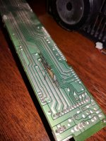
Actually, I could not find any burnt components, or any components besides three 0 Ohms resistors connecting the power and the signal ground.
However, if you have a look at the attachment, I think you will see the issue...
This track connects both grounds.
This is the trouble with these huge receivers : this thing was hidden deep inside so I never saw it.
I'll fix this today and put the receiver back together tomorrow. I will report then if the receiver works but I guess it will.
Attachments
Last edited:
Awesome find. Probably an idea to check for what blew that track out as well, as there may be another fault lurking.
I just finished putting back the receiver together and... -15V rail is gone and +15V goes up to 20V.
Guess I'll have to have another look at the regulators.
Guess I'll have to have another look at the regulators.
- Status
- Not open for further replies.
- Home
- Amplifiers
- Solid State
- Denon AVC-A1SR DC Offset