I just got a spare Denafrips ARES II board. I bought it used ("in working condition") but I doubt it is the case. The initial plan was to use it in a DIY DAC perhaps with a lithium battery power supply. But first I need to power-up this board, repair it and test it. Can you help me with that ?
I am looking for information about the original transformer and how it is wire on the board (PIN 1 to 8) ?

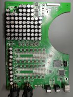
Here is the top of the board:

I already see two problems on the board :
I am looking for information about the original transformer and how it is wire on the board (PIN 1 to 8) ?
Here is the top of the board:
I already see two problems on the board :
The two center PIN of the chip (red arrow) were connected. Any clue of the chip reference ? I think it is a LDO fix the gate voltage the transistor. | On the LT1763 LDO seems defected (yellow, too much heat) |
Attachments
...

Judging by the PCB tracks thickness.... red seems to be higher current ... probably analog section windings; blue is lower current... maybe digital?
Can you show what's on the top? That will help determine what voltages you may need (and if my suggestions are correct... or completely off 🙂).
Judging by the PCB tracks thickness.... red seems to be higher current ... probably analog section windings; blue is lower current... maybe digital?
Can you show what's on the top? That will help determine what voltages you may need (and if my suggestions are correct... or completely off 🙂).
Thanks for the picture ! Is it your DAC ? Could you take me a picture of the transformer information ? It will help me a lot.
Last edited:
...
View attachment 1097431
Judging by the PCB tracks thickness.... red seems to be higher current ... probably analog section windings; blue is lower current... maybe digital?
Can you show what's on the top? That will help determine what voltages you may need (and if my suggestions are correct... or completely off 🙂).
Thanks for this input ! I am still looking to find a picture of the transformer to know the input AC voltage.
The top is the red circle. PINs are on the bottom.
They should go to the diodes on the TOP.
Last edited: