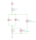
To give my new oscilloscope a test, I have been measuring some things, and thought it might be useful to show what happens when you place capacitors of different values in parallel, as is often done to try to compensate for the inductance of big electrolytic capacitors. The setup is very simple:
Physically, it looks like this:
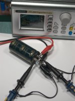
Note that the probes must be connected as close to the capacitor terminals as possible. Even a few mm of wire in between will add enough inductance to upset the measurements. The resistor is a standard metal film type, which has a little inductance of its own, but it should be less than a typical capacitor, so I'm going to pretend it's a pure resistance.
The AC source is a signal generator. It has a 50Ω output impedance, so it can cope with the very small load, as long as the output voltage is not too high. I set it to 1Vp-p for this, or about 0.35Vrms, with a 2V DC offset to keep the electrolytic capacitor forward-biased. Since the reference resistor in series with the capacitors is 1Ω, the impedance of the capacitors can be calculated simply as the ratio of the voltage across the resistor to the voltage across the capacitors. To take the measurements, I used 10x probes, as the capacitance of the 'scope is otherwise big enough to affect the measurements. I swept the signal generator from 100kHz to 20MHz, and recorded the spectrum in peak-hold mode. For example, the recorded values for one capacitor:
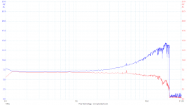
As you can see, it gets a bit ragged at the upper end, because the number of spectrum bins is larger than the number of measurements the 'scope took. That could be improved by making the frequency sweep slower (at the cost of time), or reducing the number of spectrum bins (at the cost of frequency resolution). I couldn't work out any way to get the PicoScope software to do maths on a captured spectrum, so I exported the data into Veusz for manipulation and charting. As described above, the impedance is simply (A-B) / B
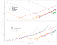
The results are noisy - no good for getting precise values, but good enough to show the shape. I could have improved that by using a higher amplitude signal. The top chart contains the results for the capacitors individually. They look about what you would expect, with the big electrolytic being inductive already where the axis starts at 200kHz. The small capacitors are still capacitive at the start, with the impedance sloping down until the self-resonant frequency, then they go up again, but lower than the electrolytic because their inductance is lower. The ceramic capacitor can be seen to have the lowest inductance. There are some small peaks at around 17MHz - I don't know what they are from.
The second chart is the interesting one, with the impedance of the big capacitor in parallel with each of the small ones. Although they give the desired result of reducing the total inductance, every single one of them has a significant peak where the capacitance of the small capacitor resonates with the inductance of the big capacitor. Note that I deliberately chose components that would show up this problem. A really big, low ESR, inductive capacitor in parallel with a much smaller capacitor is the worst case. Counter-intuitively, better capacitors are worse, as shown by the C0G device, which has the sharpest resonance due to having the lowest ESR and ESL.

Physically, it looks like this:

Note that the probes must be connected as close to the capacitor terminals as possible. Even a few mm of wire in between will add enough inductance to upset the measurements. The resistor is a standard metal film type, which has a little inductance of its own, but it should be less than a typical capacitor, so I'm going to pretend it's a pure resistance.
The AC source is a signal generator. It has a 50Ω output impedance, so it can cope with the very small load, as long as the output voltage is not too high. I set it to 1Vp-p for this, or about 0.35Vrms, with a 2V DC offset to keep the electrolytic capacitor forward-biased. Since the reference resistor in series with the capacitors is 1Ω, the impedance of the capacitors can be calculated simply as the ratio of the voltage across the resistor to the voltage across the capacitors. To take the measurements, I used 10x probes, as the capacitance of the 'scope is otherwise big enough to affect the measurements. I swept the signal generator from 100kHz to 20MHz, and recorded the spectrum in peak-hold mode. For example, the recorded values for one capacitor:

As you can see, it gets a bit ragged at the upper end, because the number of spectrum bins is larger than the number of measurements the 'scope took. That could be improved by making the frequency sweep slower (at the cost of time), or reducing the number of spectrum bins (at the cost of frequency resolution). I couldn't work out any way to get the PicoScope software to do maths on a captured spectrum, so I exported the data into Veusz for manipulation and charting. As described above, the impedance is simply (A-B) / B

The results are noisy - no good for getting precise values, but good enough to show the shape. I could have improved that by using a higher amplitude signal. The top chart contains the results for the capacitors individually. They look about what you would expect, with the big electrolytic being inductive already where the axis starts at 200kHz. The small capacitors are still capacitive at the start, with the impedance sloping down until the self-resonant frequency, then they go up again, but lower than the electrolytic because their inductance is lower. The ceramic capacitor can be seen to have the lowest inductance. There are some small peaks at around 17MHz - I don't know what they are from.
The second chart is the interesting one, with the impedance of the big capacitor in parallel with each of the small ones. Although they give the desired result of reducing the total inductance, every single one of them has a significant peak where the capacitance of the small capacitor resonates with the inductance of the big capacitor. Note that I deliberately chose components that would show up this problem. A really big, low ESR, inductive capacitor in parallel with a much smaller capacitor is the worst case. Counter-intuitively, better capacitors are worse, as shown by the C0G device, which has the sharpest resonance due to having the lowest ESR and ESL.
I find your evaluation plausible. Great work.
I do not call low ESR capacitors "better", and try to avoid them like the plague.
I do not call low ESR capacitors "better", and try to avoid them like the plague.
So a carefully chosen bypass can improve RF performance, but either does nothing at all for audio or makes things worse. This is, of course, exactly what theory says should happen. Useful to see yet another demonstration of this, yet I fear that the bypass fans will not be convinced.
You're right, I could have worded that better. Capacitors that are closer to an ideal capacitor are not always better. Sometimes parasitics are beneficial, or even required for a circuit to work....I do not call low ESR capacitors "better", and try to avoid them like the plague.
Could you expand on this? Provide an example of what you’d consider low vs not low ESR?I do not call low ESR capacitors "better", and try to avoid them like the plague.
Thanks to TS. I work with devices up to several MHz band and my practice agrees with DF96 conclusion.
Last edited:
'Low ESR' could mean 'lower than average ESR' i.e. lower than an average capacitor of a similar type.
'Low ESR' could mean 'sufficiently low that it does not sufficiently damp an unwanted resonance in my application of this capacitor'.
'Low ESR' could mean 'sufficiently low that it does not sufficiently damp an unwanted resonance in my application of this capacitor'.
What do the graphs look like up to 100khz?
The smaller capacitors do indeed just keep going up to the left, so I won't bother showing those. The big one is a litle different, and might be worth seeing.My guess is that they look just like a capacitor of the specified value.
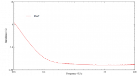
Although it has the lowest ESR of all the tested capacitors on an absolute scale, at about 20mΩ, the ESR is the highest relative to its reactance at the self-resonant frequency. That means that from where it stops being capacitive up to where it starts being inductive is very wide. Only from about 100Hz and down does it start looking like a capacitor.
I used a higher amplitude test signal of 5Vp-p and 1x probes for this one, which reduced the noise a lot.
Nice.
I have made such measurements some time ago:
< http://www.hoffmann-hochfrequenz.de/downloads/experiments_with_decoupling_capacitors.pdf >
cheers,
Gerhard
I have made such measurements some time ago:
< http://www.hoffmann-hochfrequenz.de/downloads/experiments_with_decoupling_capacitors.pdf >
cheers,
Gerhard
Thanks. I was looking for an example in a familiar (audio) / simplified / standard application in an honest attempt to better understand. That’s kind of like answering “I prefer a car that is slower than the average car in a similar price range and engine size for a given driving style and geographic locale in instances where it might be advantageous.” To “why do you like slow cars and can you provide an example of when its slowness is useful to you?” It walks around the subject but does not illuminate it.'Low ESR' could mean 'lower than average ESR' i.e. lower than an average capacitor of a similar type.
'Low ESR' could mean 'sufficiently low that it does not sufficiently damp an unwanted resonance in my application of this capacitor'.
Can you provide an example, such as in a power supply or cathode bypass capacitor or other area that many here attempt to utilize a film cap with a Electrolytic? What about replacing the Electrolytic with same value film capacitor? I imagine avoiding low esr does not imply searching for the highest esr, there must be upper and lower boundaries? He seemed also to insinuate a general distaste, not application specific.
I believe I read some information in Morgan Jones’ book that advocates a low value film cap in the order of 1/100th in parallel with an Electrolytic. This seems to be commonly quoted as logic for this practice. I’ll have to take another look as I’m likely misunderstanding a critical piece of information. Perhaps the RF performance of the bypass capacitor is of utility in tube circuits?
Last edited:
When I was decoupling early NE5539 video amplifier opamps, I found it best to use no more than x100 steps in value eg 10uF+100nF+1nF Something like 10uF+10nF and I got a wobble in the swept frequency response These were THT capacitors in those days
In many audio capacitor applications ESR does not matter very much, although that does not seem to stop people worrying about it.
ESR will always be an issue when a cap is 'bypassed', as it is usually ESR which dampens the parallel resonance. ESR may matter in a PSU with high ripple currents, because it adds to heating and may increase ripple. In each case the designer needs to think. To determine whether a particular circuit requires some ESR involves some reverse engineering - it is not really open to 'recipe' level 'engineering'.
ESR will always be an issue when a cap is 'bypassed', as it is usually ESR which dampens the parallel resonance. ESR may matter in a PSU with high ripple currents, because it adds to heating and may increase ripple. In each case the designer needs to think. To determine whether a particular circuit requires some ESR involves some reverse engineering - it is not really open to 'recipe' level 'engineering'.
spaceistheplace,
low ESR has come to be regarded as the principal indicator of capacitor quality.
Low ESR means higher instability and distortion. Without relying on numbers, I only use film capacitors and older production electrolytics from venerable manufacturers with a fairly high volume to capacitance ratio. In reality, ESR is never too high, but it does not alone ensure good performance.
😕 🙄
like this shitty electrolytic in my paper above?
Manufacturer is Murata btw.
OMG,
Gerhard
like this shitty electrolytic in my paper above?
Manufacturer is Murata btw.
OMG,
Gerhard
Last edited:
Only for people making SMPS (right) and some audiophiles (wrong). ESR is a parameter; sometimes you need low ESR and sometimes you need high ESR.N101N said:low ESR has come to be regarded as the principal indicator of capacitor quality.
Not sure what you mean. Film caps typically have extremely low ESR.N101N said:Low ESR means higher instability and distortion. Without relying on numbers, I only use film capacitors and older production electrolytics from venerable manufacturers with a fairly high volume to capacitance ratio.
A high volume to capacitance ratio means low charge density and high resistance. I use nice sounding bulky high ESR film caps and avoid contemporary electrolytic caps. Tantalum and ceramic caps have extremely low ESR and produce terrible distortion.
Two completely unconnected ideas in one sentence.N101N said:Tantalum and ceramic caps have extremely low ESR and produce terrible distortion.
Most ceramic caps have low ESR (in the audio range)
Some ceramic caps have high distortion (although not all C0G/NP0 are very linear).
No connection between these two statements.
- Status
- Not open for further replies.
- Home
- Design & Build
- Parts
- Demonstrating the pitfalls of paralleling capacitors