I use the delta mass method, but I use Blu-tak (a non-hardening slightly sticky mastic used to temporarily attach drawings to walls and similar). A ring of this can (carefully!) be fitted around the dust cap and gently pressed into place so it doesn't vibrate.
I have one of the small digital scales with a resolution of 0.1 gram, bought from Maplin here in the UK, but I guess most countries will have something similar on sale. This avoids the rattling issues I had when using coins as the weight. Also the Blu-tak usually sticks well enough do perform the testing with the speaker vertical.
I have one of the small digital scales with a resolution of 0.1 gram, bought from Maplin here in the UK, but I guess most countries will have something similar on sale. This avoids the rattling issues I had when using coins as the weight. Also the Blu-tak usually sticks well enough do perform the testing with the speaker vertical.
Hi oldbar
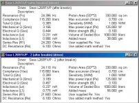
Here are the result below. Top driver is my first L26, the seond one (broken in today) the bottom. Both drivers had 6 hours breakin (warble centered on 30Hz with a 10Hz oscilating offset). TS/ specs are almost the same. Driver Vas = 115 litres on both samples and Q somewhat higher than manufacturer specifications.
Cheers,
David.
I was just wondering how did you go when you measured your second driver.
Here are the result below. Top driver is my first L26, the seond one (broken in today) the bottom. Both drivers had 6 hours breakin (warble centered on 30Hz with a 10Hz oscilating offset). TS/ specs are almost the same. Driver Vas = 115 litres on both samples and Q somewhat higher than manufacturer specifications.
Cheers,
David.
Attachments
One thing I forgot to mention, although I have the driver clamped to a tapered piece of 4x2, it is currently pointing at a wall about 1.5 metres away. I'm hoping the reflection off the wall won't change the impedance curve and resonant peak much, although it should be consistent between measurements therefore Vas should be the same. (ie. if I have artifically increased Fs from the resistive "loading" of the wall opposite the driver face - it will be increased by the same factor for both before and after mass impedance measurements).
david.
david.
Dave Bullet said:One thing I forgot to mention, although I have the driver clamped to a tapered piece of 4x2, it is currently pointing at a wall about 1.5 metres away. I'm hoping the reflection off the wall won't change the impedance curve and resonant peak much, although it should be consistent between measurements therefore Vas should be the same. (ie. if I have artifically increased Fs from the resistive "loading" of the wall opposite the driver face - it will be increased by the same factor for both before and after mass impedance measurements).
david.
That will not change the result at all.
The funny thing is, my enclosure modeling with my wildly different results is exactly the same. This is what Vance says in his LDC book (that the process of driver breakin doesn't change enclosure alignment targets but is used to confirm you have a good driver).
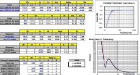
The image below shows the same driver modeled in the same enclosure with same tuning (90L to 25Hz). The red is the FR response and excursion for the L26 with my measured params. The blue (overlaid) is Seas params.
So - I can probably rest easy and continue the design.
The image below shows the same driver modeled in the same enclosure with same tuning (90L to 25Hz). The red is the FR response and excursion for the L26 with my measured params. The blue (overlaid) is Seas params.
So - I can probably rest easy and continue the design.
Attachments
Dave Bullet said:The funny thing is, my enclosure modeling with my wildly different results is exactly the same.
Svante said:Anyway, the value of Cms is usually not as critical as one might think. Cms has the greatest effect below the system resonances, and this range is usually the least interesting in loudspeaker design. This is not always easy to understand when looking at "high level" parameters, such as Vas, Qts and fs. A variation in Cms affects them all, and the co-variation leads to rather small differences above fs. In this case it might be easier to understand the effects through Mms, Cms and Rms/Rme instead.
😎 😎
- Status
- Not open for further replies.
- Home
- Loudspeakers
- Multi-Way
- Delta mass - Vas too small