It's unlikely that you will find a service manual for that amp. If no one has one and you still want/need help, post a photo of the board and a description of the problem.
The problem is that sometimes when the amplifier is powered on it goes into a "subgain" mode... The output of the amplifier is very weak, and it does this on all channels. Sometimes it works if I remove REM connection and sometimes I need to remove the fuses to go back into normal mode.... very weird behavior.
No, it's not muted... the output is very weak, something like 10%.
For example when this problem occurs if my HU is on 3/4 volume, the sub is hardly moving... when the amplifier works fine, on the same volume level the sub is blasting.
For example when this problem occurs if my HU is on 3/4 volume, the sub is hardly moving... when the amplifier works fine, on the same volume level the sub is blasting.
Could it be a signal problem from the head unit?
Is the fault affected by vibration or flexing of the board?
Is the fault affected by vibration or flexing of the board?
I just worked on a pair of older Directed 1200d amps. All their daughter board connections were cracked and caused them to fail. I am not sure if your amp is similar at all, but I would check them carefully. I didn't find my issue until I used a USB microscope.
I also just finished working on an Orion HCCA-d1200, also made by directed and superficially looks similar to what you have. The Orion used a PIC micro that had 0-5V analog signal from the gain pot on one of it's inputs. It in turn drove a digital pot to control the amp gain. If the PIC was not driving the digi-pot (I had removed it) then the amp defaulted to a very low gain. In the end I got rid of the PIC altogether, I lost the ability to use remote gain control as well as all the antitheft and programmable lighting crap and I made some small mods to bypass the dig-ipot and use a new 50k pot to adjust the gain directly from the panel. It works perfect but you loose some features. In my case the PIC was getting flakey and I didn't even try to source a programmed replacement. My amp is just a something I had around that I decided to fix and give to a friend so I wasn't worried about having some missing features. I don't do "customer repairs" so I don't have to worry about it not being factory exact. Your mileage may vary.
Good Luck,
Jason
Last edited:
It's not a problem of the HU or vibration issue, there are 3 digital pots.... I managed to bypass them but lost the ability to use gain control... do you have any schematic for that orion?
I don't have a schematic, but it was pretty easy to figure out. Just pull the data sheet for the digi-pot. I cut the traces going to the old gain pot and then wired it with jumpers to the high/low/wiper terminals on the digi-pot. I ended up mounting a few resistors on the bottom of the board just so I could tie into the control card pins instead of bodging wires up to the smd pot. I have some pictures, I'll see if I can dig them up and post them but it might have to be later tonight, I'm stuck on a phone atm...


Great, thanks for the pics, but I have some questions if you don't mind... where dit you cut the traces from the digi pots? Right next to them? Also, why did you put there those resistors and you changed the original gain pots or changed them?
Thanks! 🙂
Thanks! 🙂
I completely removed the PIC. I left the digi-pot, it didn't seem to cause any harm. I did not cut the digi-pot traces, I cut the original "gain pot" traces. IIRC the original gain pot had +5vdc, ground, and wiper went to the PIC. On mine it had a dual gang 10k pot, only one half of it was actually used. I cut the 5v, ground, and wiper connections at the analog pot.
The original digi-pot on mine had the low terminal tied to ground via a resistor on the little riser card. On my first try I wired in the new pot directly to the terminals on the digi-pot, it worked but it was difficult to alter jumpers directly to the smd ic and it didn't look like it would be very robust. So, I traced the needed lines to the header that connects the daughter board to the main board, that way I could run my jumps on the bottom side. I soldered directly to a few traces that I cleaned the solder mask from, just because it was easier then trying to run them all straight to the pin header. I soldered the resistors straight to nearby ground plain. The one jumper that goes through the hole in the board was because I accidentally blew the via out of that one location on the header, so I drilled a small hole and jumped up to the pin on the op amp on top.
I have a few notes scratched down in the shop on pinouts and routing. I doubt it will be much help on a different amp, but I'll try to dig them up for you later.
Good luck,
Jason
Great, thank you very much... How many gains do you have on that amp ?
I have 3 and also 3 digi pots... so mine will have 2x more wires. 🙂
I have 3 and also 3 digi pots... so mine will have 2x more wires. 🙂
I forgot to mention, the replacement gain pot is 50k, to match what my digi-pot used to be. The digi-pot is log taper, I'm not sure if I used a linear or log replacement, I had it in a drawer and it the right resistance and matched the amp so I used it.
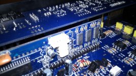
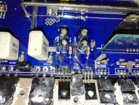
My amp is a monoblock sub amp, only one gain control. The daughter card has locations for apparently three digi-pots though with only one populated, I wonder if it uses the same daughter card as your amp... I have a picture of it somewhere. Stand by...
*edit* here you go, best one I could find of the board. This was my first attempt with jumpers straight to the digi-pot...
Last edited:
I just measured the power input of the amp witout any signal/speakers and it suck 2A... it is normal ?
I don't think that is excessive if that is what you are asking. It is 4 AB channels and one D channel, I normally see 1-2 amps of idle current on most of my AB amps. Some of my bigger amps idle a bit higher than that, but I doubt that what you are seeing is abnormal.
Good Luck,
Jason
Good Luck,
Jason
Great, also can you tell me what kind of transistors / zenners that orion is using for the regulated voltage for opamps +-15 (somebody changed them) and it seems that my voltages are not so good, on the negative side I have -14.85v and on the positive I have +17.9v.
These voltages are measured on the opamps.
Thanks in advance! 🙂
edit: I seems that I have other problems now, it will always fry that zenner (VD906) after the bd441 when I power the amp on.
These voltages are measured on the opamps.
Thanks in advance! 🙂
edit: I seems that I have other problems now, it will always fry that zenner (VD906) after the bd441 when I power the amp on.
Attachments
Last edited:
Sorry man, I am working day shift 12s right now and don't have time to open the amp back up. I'm pretty sure they are just 15V zeners, but I have no way to confirm right now. Hopefully someone else can help you. Aside from that ESP board I doubt our two amps are that similar. Maybe the class D sections are similar, but my amp has no AB section and is much smaller.
Sorry I cannot offer more insight.
Later,
Jason
Sorry I cannot offer more insight.
Later,
Jason
- Status
- Not open for further replies.
- Home
- General Interest
- Car Audio
- DEI Directed D2205