i found a compatible transistor IRF3205. could i replace with this type? the rds is about 0.008, and the original has 0.016ohm, aproximative the same current and voltage.
sorry for multiple posts but i can't edit after a period of time
sorry for multiple posts but i can't edit after a period of time
The 3205s are typically not safe to use with 100 ohm gate resistors.
What are the originals (FQP65N06s)?
Are they unavailable in your area?
What are the originals (FQP65N06s)?
Are they unavailable in your area?
the 100ohm rezistors 3 or 4 are burned. i need to change them. i can change all the restistors, but if you can recomand a type of transistor it will be perfect! i have found IRF1010, but it has the same rds value. i repeat: i can change all the resistors that they are 100ohm with a particular one to be perfect.
the original transistors costs a little bit too much... aprox 3$ each and in this case i need to change only six of them, the rest of them are ok, in a good condition. i measure them and i know that they are in a good condition. but it exists a risk, i replace 6 of them and after a while to get burned.....
the original transistors costs a little bit too much... aprox 3$ each and in this case i need to change only six of them, the rest of them are ok, in a good condition. i measure them and i know that they are in a good condition. but it exists a risk, i replace 6 of them and after a while to get burned.....
i have found a compatibile transistor IRFZ44V with 0.0165 ohm rds 60V 55A. and it has a resoanble price around 1$.... and i don't need to make modifications in the resistors part....
Or another option could be IRFZ48 thar has 12mOhm rds 72A 60V... And the differnce between the original rds value 16 and 12 is a little bit smaller.... If you know another type of transistor i will be very happy
I think the two supplies need to be as closely matched as possible and using the original FETs would do this. If you absolutely won't/can't buy the originals, the Z48 (with 68 ohm gate resistors) or the IRF1010E with 47 ohm gate resistors should work.
Since only one supply failed, you could possibly have an intermittently shorted power transformer. Before you do any further repairs, power the amp up via a 15 amp fuse to confirm that it will power up through that fuse without blowing it. After replacing the FETs and resistors, clamp all transistors tightly against the heatsink and power the amp up (again through the 15 amp fuse). If the fuse doesn't blow, twist/push/pull on the transformer in the failed supply to see if the amp every blows the fuse or draws excessive current. If it does blow the fuse, you'll need to find the short in the transformer windings.
Since only one supply failed, you could possibly have an intermittently shorted power transformer. Before you do any further repairs, power the amp up via a 15 amp fuse to confirm that it will power up through that fuse without blowing it. After replacing the FETs and resistors, clamp all transistors tightly against the heatsink and power the amp up (again through the 15 amp fuse). If the fuse doesn't blow, twist/push/pull on the transformer in the failed supply to see if the amp every blows the fuse or draws excessive current. If it does blow the fuse, you'll need to find the short in the transformer windings.
i will change all the transistors with irfz48, and the resistors. i search and i discoverd that the itfz48 has 0.016ohm rds current... in this case i don't need to make any modifications at the 100ohm resistors. can anybody say what type of driver transistors are(i reffer to the transistors that commands the 100ohm resitors to the gate? on them is typed A1266Y. i want to know to buy them in case of something because the order takes some time.....
thanks very much.
thanks very much.
Last edited:
The Rdson has nothing to do with the gate resistor value. The input capacitance determines the required gate resistor value. I'd recommend replacing the 100 ohm resistors.
2SA1266 or KTA1266
2SA1266 or KTA1266
Hello. I have changed the transistors with irfz48N and the resistors with 68ohm. The amp fuction well, but when a hit a little bit one choper of the coopers(not both, one is perfect) the amps enter into the protection mode, and after a couple of seconds the protection shuts down and everything comes back to life.
I measure the voltage between the ground and the first pin of each transistor. in some cases i have found 3.02V and in other cases i have found 3.41V if i remember where the transistors were burned i have found this voltage. I changed all the 100ohms resistors with 68ohm that are put one the first pin of the transistor. The transistors stays cold during to the tests, i put a fuse on the wire but the maximum consume was about 7A.
As you said probably the cooper has a problem. I will get it out and i will check. I am happy because the protection takes the right measures and it shutdown in time.
I have serveral questions:
1. if i fouund where the wire from the cooper is broken can I solder? or it needs to be changed? Cand i change the wire with a similar one with PVC insolation?
2.I have found one part of the amplifier a litle bit warm in comparasion with the oposite part of the amp. It is normal?
hello.
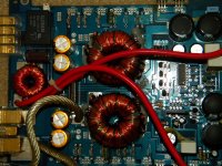
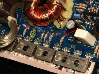
i have a big-little problem. where i found the burned transistors now after i replaced all the transistors and all the 100ohm resistantces with 68 ohm and i found 4 of 220Ohm(the green one) and i changed those, i have on the first pin of 3x2 transistors( 2 groups of 3 transistors) 3.57V, on the others i found 3.07V(3x2). My problem is that those that have a bigger voltage on the gate is getting hot. i attached a photo will al the modifications in the power supply area.
I forgot to say: on the second pin of each transistor i found the same voltage(~9.5V) and on the third pin i have found 0V, all the measures are with the black probe on the minus of the power supply.
What is the problem in this case???? HELP!!!!!
Attachments

Last edited:
about 7 Amps. A big power supply. This can't affect only a half of the amp... i reffer to the voltage of half of the transistors. the rest is ok, 3.07V....if the power suplly is not able to give all the current needed will affect the entire amp.
driver circuit is KIA494AP and the driver transistors A166
driver circuit is KIA494AP and the driver transistors A166
Last edited:
For the transistors that have 3.57v on the gate legs, what is the DC voltage on the end of the 68 ohm gate resistors that is NOT connected to the first leg of the FET?
do you say to disconnect one of the 68 resistor fron the gate of the transistor and to measure the voltage?
all the 68 ohm are directly conected to the gate of each transistor. the 220 ohm are conected to the source of a group of 3 transistors. i can't understand what to measure!!
i measure on the output of the driver circuit, on the pin 9 i have 3.3V and on the other i have 3.7V. i think that the driver circuit has a problem.....😀
- Status
- Not open for further replies.
- Home
- General Interest
- Car Audio
- Defect Transistors in Hifonics Brutus BX1500D